Analyzing, locating, and repairing circuits is a basic task for hardware engineers. Various strange problems always arise on-site, and we need to gradually locate and solve these issues to reduce failure rates, improve production line yield, increase mean time between failures, and minimize after-sales issues. This section introduces several common analytical approaches that are applicable in hardware circuits such as smartphones, tablets, and computers.
In my daily work, I have noticed that some colleagues rush to replace the board without identifying the root cause of the problem. Although the issue may not appear afterward, the root cause remains unidentified, which is always a hidden danger. If the problem resurfaces during after-sales service, the consequences could be unimaginable. This section introduces several common circuit problems and their analytical and corrective approaches. Once again, I emphasize that when encountering a problem, it is crucial to identify the root cause.
I once worked with a company’s product that used an IMU sensor unit, which detects angular velocity and angular acceleration, also known as A+G (accelerometer and gyroscope). The IMU unit is essential in current smartphones, and for products like drones, it is one of the necessary components for inertial navigation. During their trial production, they found that several boards had abnormal functions, and it was ultimately discovered that replacing the IMU chip restored normal function, leading to the conclusion that the IMU chip was faulty. The company was relatively small, and their R&D system was not mature, so this issue was not followed up further.
In fact, the malfunction caused by the IMU chip was merely a surface phenomenon. When I communicated with them, I asked whether the chip was defective or if there was an issue with the peripheral circuit, whether it was a cold solder joint or a detached solder joint, and whether it was caused by structural stress or electrical stress. They were unable to answer these questions because they had not identified the root cause, and thus did not make targeted modifications. This is a hidden danger, and later I helped them develop a set of R&D processes to standardize the tracking of trial production issues.
So what are the common root causes for such problems? How can they be modified?
1. Poor soldering – Short circuit.
During SMT in the factory, it is possible to cause localized solder bridging. The amount of bridging may not be significant at first, so the system operates normally initially. However, as the temperature rises or the board vibrates, the bridging begins to affect the circuit, leading to abnormal circuit operation.
2. Poor soldering – Cold solder joint.
This is also a common soldering issue that many colleagues have encountered. Some ICs do not work normally, but after resoldering, they can function correctly, which is likely due to a cold solder joint.
3. Vibration causing cold solder joints.
Our PCB circuit boards inevitably experience vibrations during use, such as motor vibrations in phones, propeller vibrations in drones, or everyday drops. These high-frequency vibrations can cause components to detach or exacerbate the cold solder joint phenomenon. Therefore, during trial production, to eliminate abnormalities caused by these vibrations, smartphone development often involves dropping numerous phones to identify the problematic locations for corrective action.
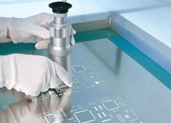
4. Vibration causing chip damage.
This can sometimes be seen clearly under a microscope, where cracks can be observed on the chip surface. Sometimes there may be no visible abnormalities, but the chip may be damaged internally. In such cases, the chip manufacturer needs to conduct root cause analysis, so engineers typically perform visual and impedance checks on abnormal ICs, and those responsible for the structure need to analyze whether the chip is located in stress-sensitive areas.
5. Chip burnout.
Some of these can be observed under a microscope, while others cannot. For products with very tight project schedules, it is necessary for both the chip manufacturer and product parties to analyze the problem together, eliminating their own circuit and IC issues in a synchronized manner.
6. Counterfeit chips.
Without further ado, some online e-commerce platforms have counterfeit refurbished chips. For product development, it is recommended to purchase chips from legitimate channels, such as the chip agency I often use, Yunsil (Chengdu) Technology Co., Ltd. They are a first-level agent for original manufacturers, ensuring the quality of chips and allowing for free sample testing, which is very convenient.
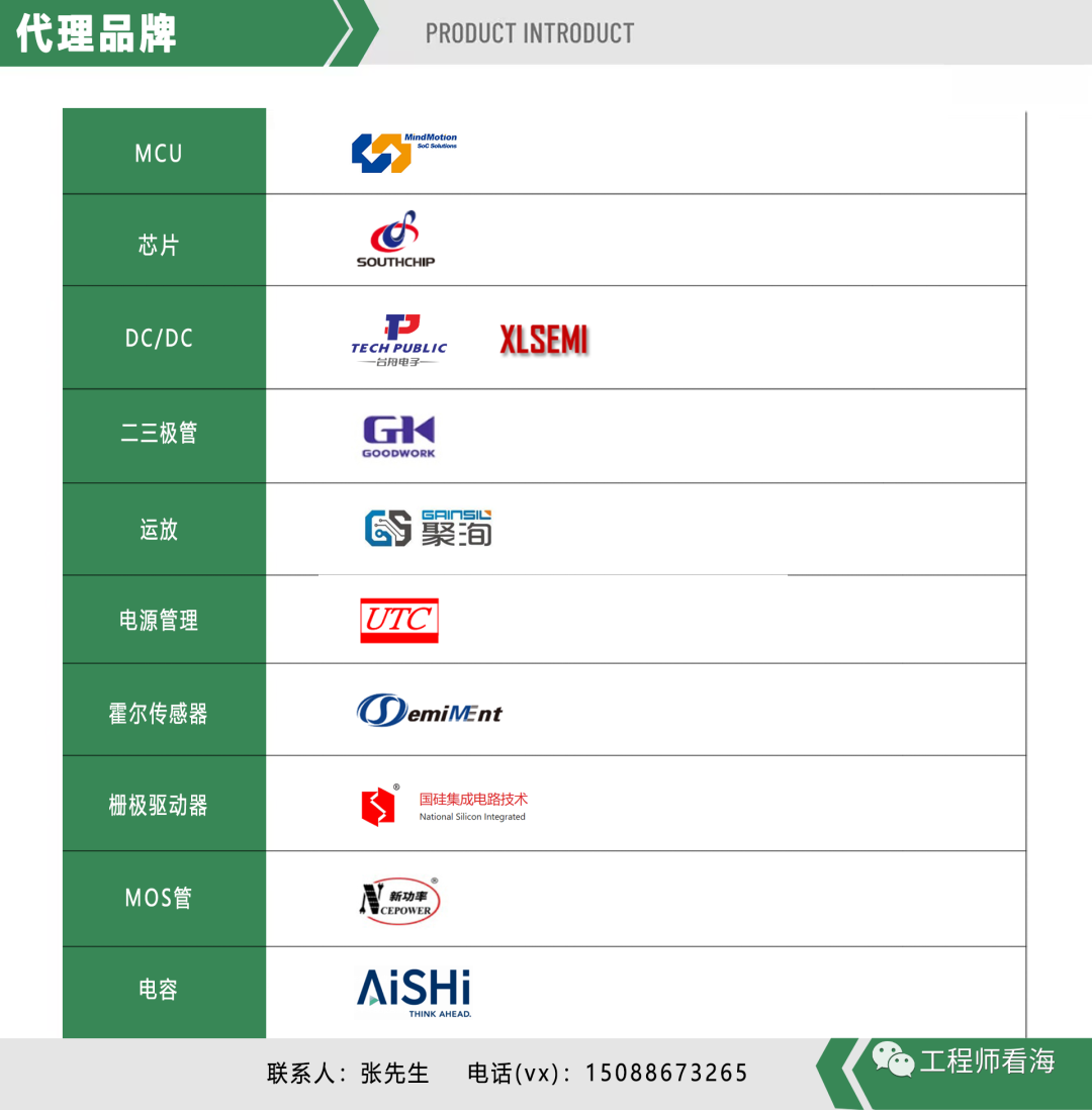
Lingdong Micro: MCU microcontroller
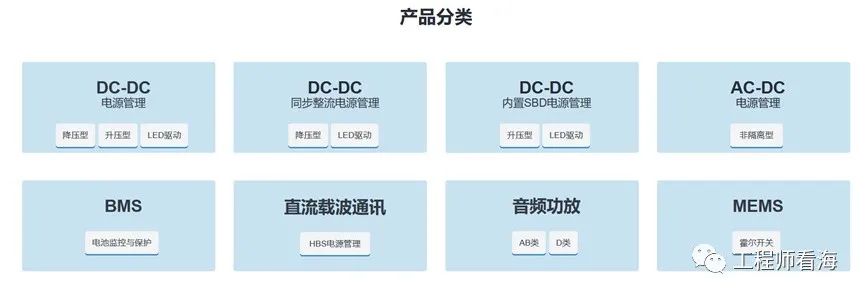
Nanchip: AC-DC chips, DCDC chips
Taizhou Electronics: DC/DC (replaceable for some TI models) ESD small power MOS transistors, RF switches
Xinchip Semiconductor: DC/DC (high cost-performance ratio), audio amplifiers, and MEMS
Saizhu Electronics: switch Hall, linear Hall, magnetic encoder chips, current sensors
Good Work: diodes, transistors, TVS tubes, rectifier bridges
Juxun: operational amplifiers, precision operational amplifiers
UTC( Youshun): power management, power drivers, LED driver chips, LED power supplies, operational amplifiers, comparators, digital amplifiers, logic IC
GuoSilicon: gate drivers
New Clean Energy: various MOS transistors
Aihua Group: electrolytic capacitors
7. Chip itself has issues.
Chips also have production batches, and there may be differences in the production environment for different batches, which may lead to issues with a particular batch of chips.
Short circuits and cold solder joints are both related to soldering. The methods for determining whether there is a short circuit or cold solder joint are also quite simple. Generally, resoldering and cross-validation can be performed. If applying some soldering flux and resoldering results in normal operation, it is likely related to soldering. If resoldering does not work, cross-validation can be conducted by swapping suspected problematic ICs from the abnormal board with the normal ICs from the functioning board.
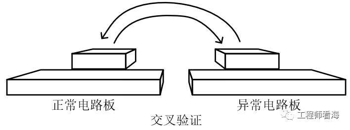
If both circuit boards are normal after cross-validation, it is likely related to soldering. If the normal board becomes abnormal after soldering the abnormal IC, while the abnormal board becomes normal after soldering the normal IC, then the problem follows the IC, indicating it is likely an IC issue. If the normal board remains normal after soldering the abnormal IC, and the abnormal board remains abnormal after soldering the normal IC, then the issue may follow the circuit board.
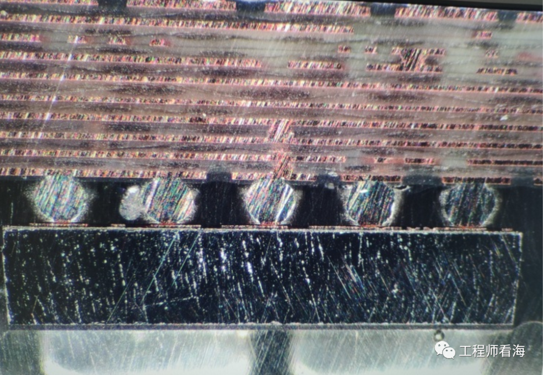
The corrective direction for soldering issues is also quite similar. Several abnormal circuit boards can be examined using 3D X-ray or cross-sectioning to observe the soldering conditions, followed by targeted corrective measures, such as controlling soldering temperature, adjusting the stencil to modify solder volume, or fine-tuning component positions to avoid short circuits. The image below shows that the solder balls of the IC are not fully contacting the PCB circuit board, indicating a need for optimization.
Some products work normally but break after being dropped. In such cases, it is essential to disassemble and analyze what broke, then adjust based on the stress distribution of the circuit board. Some chips are large and glass-encapsulated (appearing shiny), making them sensitive to force. We should avoid placing such chips in positions where the board is prone to twisting or high stress. Instead, we can try relocating the layout or adding reinforcement on the PCB opposite the chip to alleviate circuit board deformation. Alternatively, we can add cushioning pads behind the chip, although relocating the chip layout would be the best solution. Many simulation software tools can perform force simulations, allowing us to optimize layouts in advance to minimize such issues.
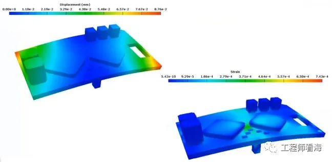
(Image from Anshi Asia Pacific)
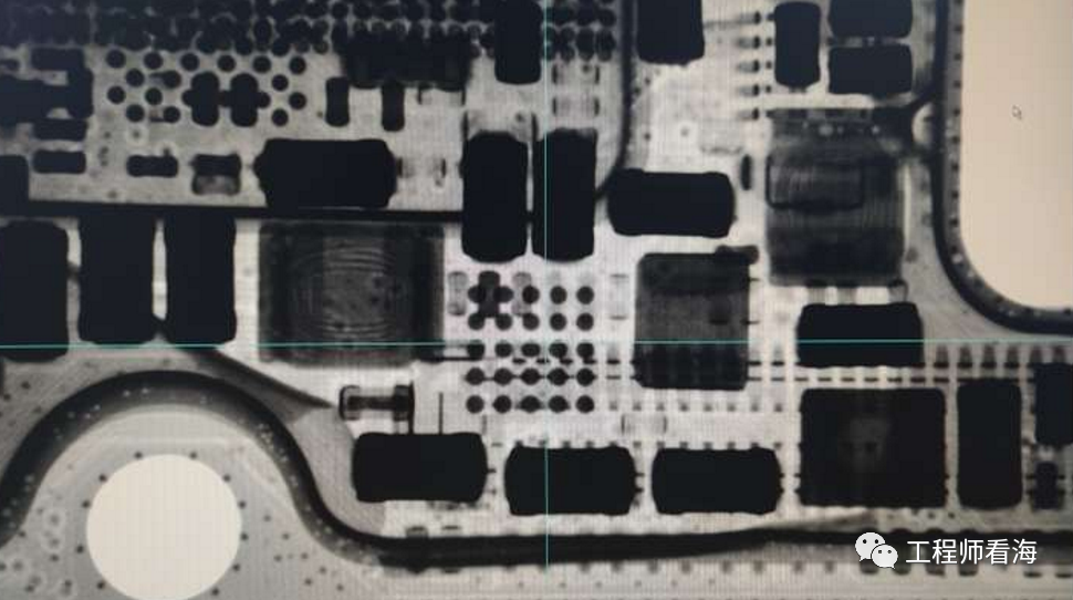
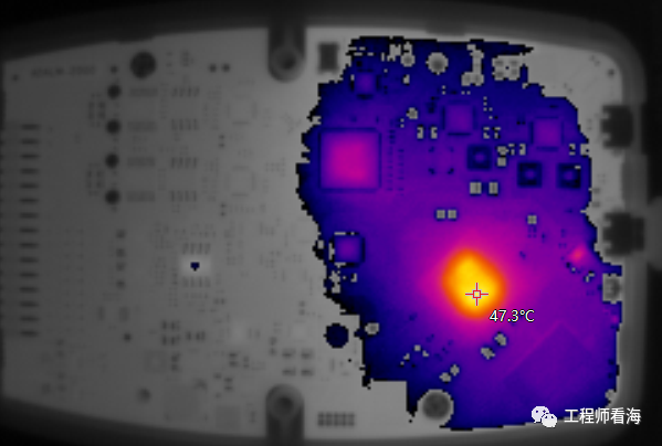
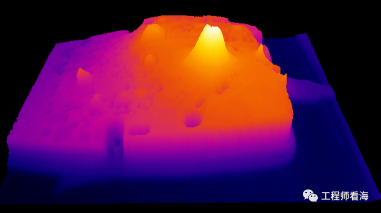
An infrared thermal imaging camera is one of the commonly used devices during hardware debugging, making it convenient to locate short circuit positions. Sometimes, when powered on, the infrared imaging camera can directly show the short circuit location, which is much faster than testing each component individually or disassembling. If the short circuit current is too small or the PMIC power module has implemented short circuit protection, hotspots may not be visible. In this case, you can use an external power supply to inject current into the power network with abnormal impedance to ground. For example, using a 100mA current source to inject current into the circuit board (for computer PC motherboard analysis, several amperes of current are often injected), making it easier to observe hotspots for short circuits or breakdowns.
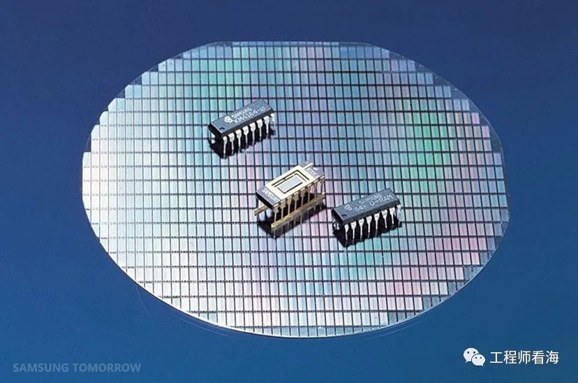
If the chip is indeed faulty, we also need to analyze why the chip failed. Chips come in batches, and we provide the chips to the chip design manufacturers for them to analyze the specific reasons for the chip failure. We should not attempt to analyze it ourselves, as each field has its expertise. For instance, I once encountered a situation where a particular batch of chips had wafer contamination issues, leading to probabilistic anomalies in that batch. We all know that the chip manufacturing process has very high environmental requirements, and IC manufacturers can even trace chips back to the exact position on the wafer. If there are issues with this batch of chips, it is necessary to isolate them promptly to prevent problematic chips from mixing with normal ones and to manage materials reasonably.
This concludes the analysis and repair thoughts for hardware circuit boards (1). I hope everyone avoids the sixth point; it’s truly infuriating!
If you’ve read this far, please like, bookmark, and share!
Limited time offer to scan the code to join the group and exchange more industry technology

Recommended Reading▼
Batteries, Power Supplies
Selected Hardware Articles
Huawei HiSilicon Software and Hardware Development Materials