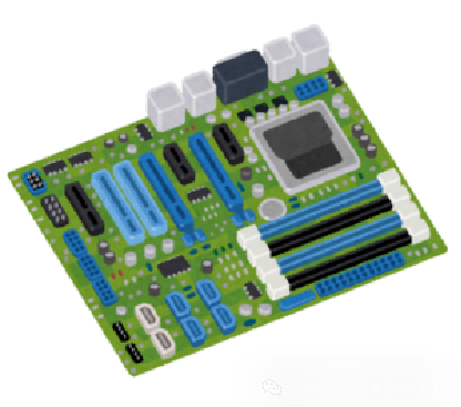
What is a printed circuit board?
A printed circuit board is a circuit formed by arranging conductive metal lines on an insulating substrate.
In simple electronic projects, reconfigurable circuit boards such as breadboards or universal boards are often used, while printed circuit boards are fixed substrates that have these circuits pre-manufactured.
The greatest advantage of using printed circuit boards is the ability to produce the same circuit at a “low cost” and in “large quantities”, making them an indispensable component in the development of modern electronic devices.
Composition of Printed Circuit Boards
Printed circuit boards are constructed by layering different materials to form the circuit.
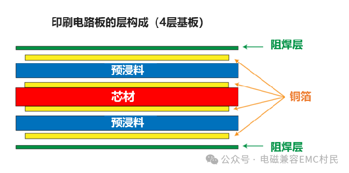
The materials required to form the circuit include the following four types.
Copper foil
Core material
Prepreg
Solder mask
Each of these four layers serves different functions.
Copper foil (conductive layer)
Due to its conductive properties, copper foil is responsible for transmitting circuit signals. In standard printed circuit boards, copper foil with a thickness of about 35 microns is typically used, but depending on the strength of the signal current, thicker copper foil (over 70 microns) may also be used. Thickness is measured in ounces (oz), where 35 microns = 1 oz.
Core material (insulating layer)
The core material is the insulating substrate that forms the basis of the printed circuit board, primarily serving to maintain the insulation between the layers of the printed circuit board. The choice of core material is crucial as different materials can lead to variations in price and performance.
Prepreg (bonding layer)
Similar to the core material, prepreg is used to maintain insulation between layers while also providing additional bonding functionality. It is made of glass fiber cloth impregnated with resin, which softens when heated to act as an adhesive.
Solder mask (surface protective film)
The solder mask is a coating used to insulate and protect the surface of the printed circuit board. Typically, printed circuit boards are green because the solder mask is green. While green is the most common color, other colors such as red, blue, yellow, black, and white are also available.

The reason for using green includes its high visibility, making it easier to detect defects during inspection, but recently, colors can be chosen based on personal preference.
Classification of Printed Circuit Boards
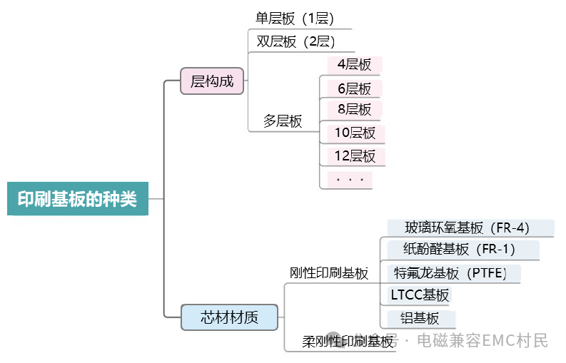
Printed circuit boards can be classified from two perspectives: “layer structure” and “core material type”.
Classification by Layer Structure
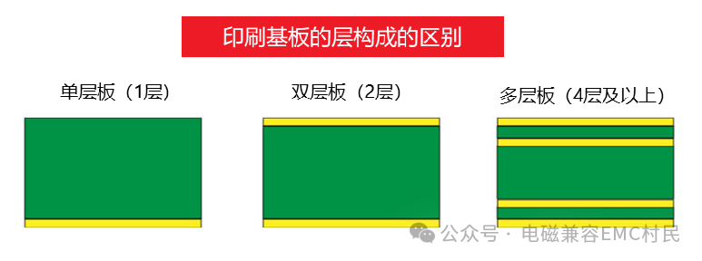
Layer structure is classified based on the number of conductive layers.
Single-sided board
A single-sided board refers to a printed circuit board that has a conductive layer on only one side, either the front or the back. Since the cost generally increases with the number of layers, it is often used in lower-priced electronic devices.
Double-sided board
A double-sided board is the most basic type of layer structure, with conductive layers on both the front and back surfaces, centered around the core material. It is compatible with both through-hole and surface-mount electronic components, making its high adaptability one of its advantages.
Multi-layer board
Multi-layer boards are used for circuits with many signal lines, existing in configurations such as “4 layers”, “6 layers”, “8 layers”, “10 layers”, and “12 layers”. The differences in these layer counts are based on the scale of the circuit; for example, general-purpose computer boards like Arduino use 4-layer boards, while high-functionality computers like smartphones use 8-layer or 10-layer boards.
Generally, increasing the number of layers tends to raise costs.
Classification by Core Material Type
The core material is mainly divided into two categories: “rigid substrates” and “flexible substrates”.
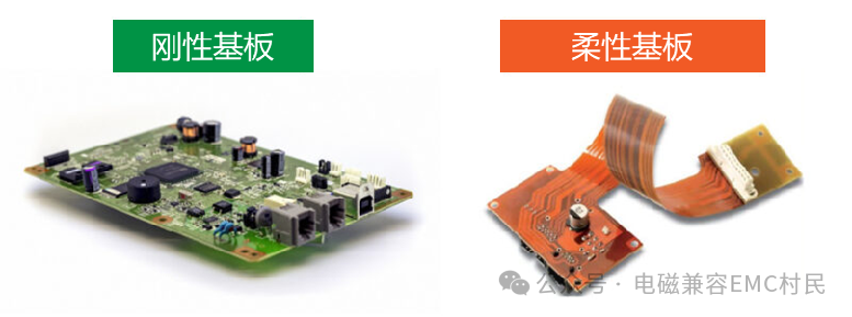
These two substrates differ in the hardness of the core material; rigid substrates are hard and not easily bent, while flexible substrates are soft and deformable. Rigid substrates are used in most cases, but flexible substrates are adopted when bending along the casing of electronic devices is required.
Additionally, flexible circuit boards are often used as connecting cables in mobile devices such as smartphones and digital cameras due to their thinner profile.
Types and Characteristics of Printed Circuit Boards
Glass epoxy substrate (FR-4)
Glass epoxy substrate is a type of rigid substrate made from woven glass fiber impregnated with epoxy resin. It is the most widely used in printed circuit boards and is often referred to as glass epoxy substrate.
Advantages
The characteristics of glass epoxy substrate include its low cost.
This is related to its widespread use; due to high circulation, the unit price is easily reduced. Furthermore, in terms of circuit board construction, it is not only easy to produce single-sided boards, but double-sided and multi-layer boards are also easy to manufacture, and it has excellent flame retardancy and durability, making it a convenient material to use.
Disadvantages
On the other hand, its disadvantage is slightly poorer processing performance.
During the manufacturing process of printed circuit boards, multiple boards are usually combined on a large panel for cutting, which can easily produce burrs. These burrs may cause poor conductivity due to dust generation, so it is essential to check for dust or powder on the board during manufacturing.
Others
In high-temperature environments, materials with better heat resistance than FR-4, such as FR-5, are used. This FR-5 glass epoxy substrate is widely used in automotive applications.
Paper phenolic substrate (FR-1)
Paper phenolic substrate is a printed circuit board made from paper impregnated with phenolic resin, also known as bakelite substrate.
Advantages
Paper phenolic substrate is known as the most economical material among printed circuit board core materials, thus commonly used in low-cost electronic products and white goods.
Disadvantages
Paper phenolic substrate is typically used only as a single-sided board. This is due to its poor durability and tendency to warp, making it unsuitable for double-sided or multi-layer boards. Additionally, its flame retardancy and water absorption performance are also poor, thus it cannot be used in overly harsh environmental conditions.
Polytetrafluoroethylene substrate (PTFE)
Teflon is the trade name for the fluororesin (PTFE) sold by DuPont. You may have seen it used in products like frying pans under the name of Teflon coating.

Regarding Teflon substrates, they are particularly commonly used as printed circuit boards for high-frequency circuits. This is because Teflon’s properties as a dielectric material are very suitable for the transmission of high-frequency signals.
Advantages
Teflon has a low dielectric constant ε’ and a small loss tangent tanδ. The loss tangent is a parameter directly related to high-frequency signal loss, and having a small loss tangent is very important in electronic devices that handle high-frequency signals.
Disadvantages
Teflon substrates are significantly more expensive than standard glass epoxy substrates. Therefore, even in high-frequency applications, circuit design improvements are sometimes made to use glass epoxy substrates instead.
LTCC substrate
LTCC substrate is a printed circuit board made from aluminum oxide (ceramic) core material with added glass.

Advantages
LTCC substrates are also commonly used as printed circuit boards for high-frequency circuits. The difference from Teflon substrates is that they can configure circuit components within the substrate and can install bare semiconductor chips, among other features. Additionally, the conductive layer uses silver with high conductivity, which is one of the reasons for low signal loss.
Disadvantages
On the other hand, its disadvantages include a higher price and a tendency to develop defects and cracks. This is partly due to the characteristics of ceramic materials, but even slight impacts can cause damage, making it a challenging substrate to handle.
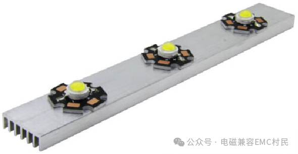
Aluminum substrate
An aluminum substrate is a printed circuit board with a metal core material.
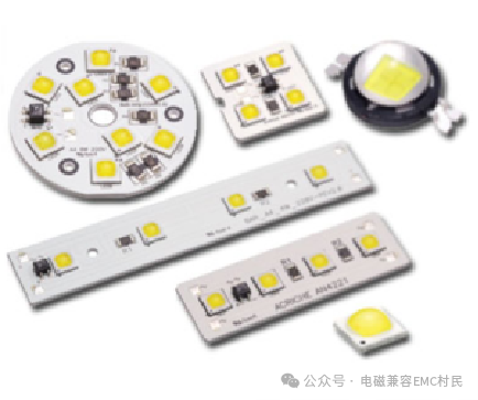
Advantages
The construction of aluminum substrates involves adhering a thin substrate to an aluminum plate, offering a relatively low price while also providing high thermal conductivity and heat dissipation.

Metals generally have high thermal conductivity, making it easy to dissipate heat generated by components throughout the substrate, which is why they are often used as substrates for LED lighting. Additionally, for single-sided substrates, installing heat sinks on the back can further enhance heat dissipation performance.
Disadvantages
For double-sided or multi-layer boards, it is possible to achieve this by layering copper foil or setting through-holes on the aluminum plate. However, such designs are rarely applied and are limited to specific uses.
Flexible circuit board (FPC)
A flexible circuit board is a printed circuit board that uses soft materials as the core layer.
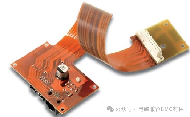
The abbreviation “FPC” comes from the English term “Flexible printed circuits” and is sometimes referred to as “flexible boards” or “flexible substrates”.
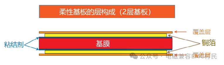
Composition
The composition of flexible substrates is similar to that of rigid substrates, but the core material is replaced with a “base film”, and the solder mask is replaced with a “cover layer”.
Advantages
The most significant feature of flexible circuit boards is that they are thin and bendable. They are often used as cables connecting printed circuit boards in narrow gaps and are almost indispensable in various electronic devices equipped with LCD screens.
Heat resistance
Due to the base film being made of “polyimide” material, it has extremely high heat resistance. Compared to glass epoxy substrates, it can be used in high-temperature environments. Additionally, the cover layer is made of a very thin polyimide film, which not only has excellent heat resistance but also outstanding insulation properties, making it very suitable for achieving lightweight designs.
Disadvantages
Although flexible circuit boards can also be used to mount electronic components, their high cost limits their practical application. More often, they are used as printable thin flexible cables.
Note: Due to reader requests to establish a WeChat group for EMC technology exchange, the group has now been created. If you wish to join the group, please scan the QR code to add my WeChat and indicate “Join EMC Technology Exchange Group”.
