Technical Article
Technical Articles
During the review of technical materials, it was found that there are some misconceptions regarding the evaluation of temperature classes for printed lines on Class I and Class II circuit boards. Additionally, some requirements in GB/T 3836.4—2021 “Explosive Atmospheres Part 4: Equipment Protected by Intrinsic Safety ‘i'” were not clearly stated, leading to questions during calculations. The latest version of IEC 60079-11 (Edition 7.0) describes this more clearly. Therefore, we will analyze this using the latest IEC as an example and explain the differences in this section of GB/T 3836.4—2021.First, when evaluating the temperature class of printed lines, several important factors must be considered, including the minimum width of the printed line, maximum allowable current, board thickness, copper foil thickness, number of layers of the circuit board, ambient temperature, and power dissipation. Additionally, the manufacturing tolerance should not exceed 10% or 1 mm, whichever is smaller.
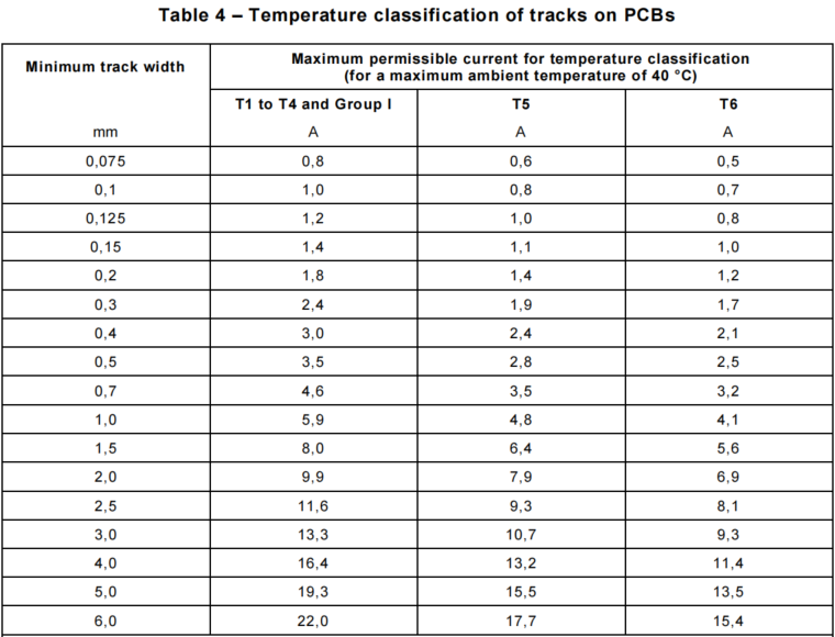
The table above specifies the maximum allowable current corresponding to different minimum printed line widths under various temperature classes. This table is applicable for a maximum ambient temperature of 40 °C, board thickness greater than 1.55 mm, single-layer circuit boards, copper foil thickness of 33 μm, and power dissipation below 0.25 W.If the above conditions are not met, the maximum allowable current must be calculated using the following formula:IP=I×λB×λL×λT×λC×λA
I is the maximum allowable current corresponding to the temperature class;
λB is the board thickness coefficient;
λL is the circuit board layer coefficient;
λT is the copper foil thickness coefficient;
λC is the component under coefficient;
λA is the ambient temperature coefficient;
The specific values of the above coefficients can be found in the table below: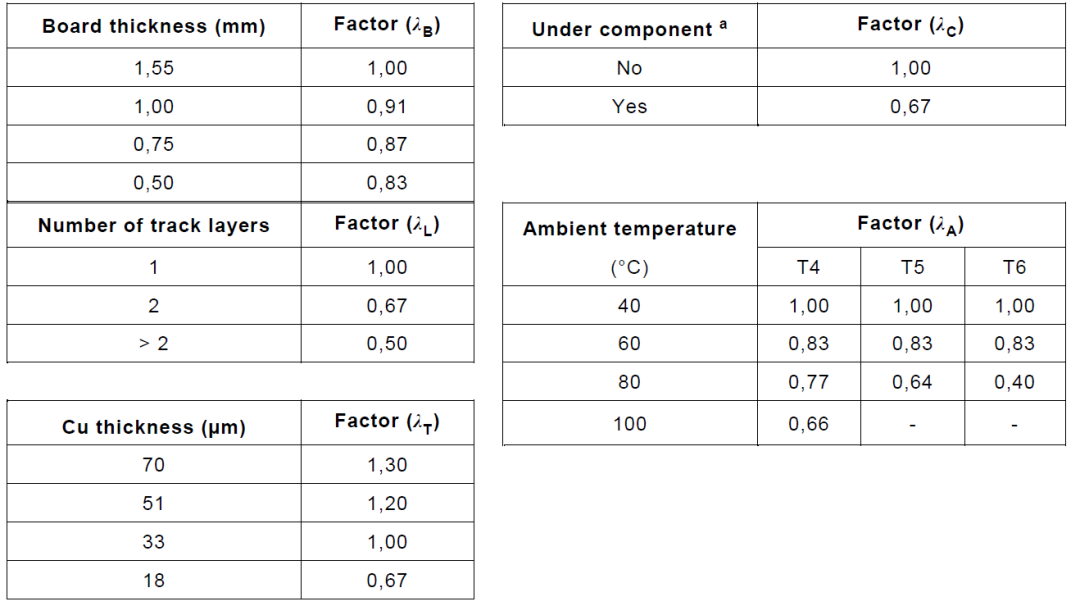
(a. indicates that when the length of the printed line under the component exceeds 10 mm, and the power dissipation under normal or fault conditions is not less than 0.25 W)
For example, when the circuit board is a 0.8 mm thick double-sided board, the printed line length exceeds 10 mm, the minimum line width is 0.2 mm, the copper foil thickness of the printed line is 33 μm, the maximum power dissipation is 0.25 W, and the maximum ambient temperature of the circuit board is 70 °C, when taking the T4 temperature class, the calculation should be as follows.IP=1.8 A×0.87×0.67×1.00×0.67×0.77=0.541 AMoreover, there are three situations where the temperature class of the printed line does not need to be evaluated according to the table:1. When the printed line length does not exceed 10 mm, the temperature class of the printed line does not need to be considered;2. When the maximum power dissipation does not exceed 1.3 W, and the maximum ambient temperature does not exceed 40 °C, the temperature class of the printed line meets T4 or Class I requirements;3. When there is no accumulation of coal dust on the surface and the maximum power dissipation does not exceed 3.3 W, with an ambient temperature not exceeding 40 °C, the temperature class of the printed line meets Class I requirements.
The calculation method of the latest IEC 60079-11 standard is multiplicative, while GB/T 3836.4—2021 adopts a divisive method. The new IEC 60079-11 has further refined the coefficients corresponding to different conditions of board thickness, copper foil thickness, and ambient temperature, making it more rigorous.
 Testing and Inspection Center: Yu AishengSpecialty:Explosion-proof electrical testing and inspectionContact:
13602056077
 WeChat has been updatedLight up the star markto receive the latest technical sharing
 Related Services


– End –
Planning: PCEC Testing and Inspection Center
Text/Image: Yu Aisheng
Review: Liu Bing, An Penghui
Editor: Meng Fanhua
Chief Editor: Jia Lei
Supervisor: Yin Hong

Statement
The copyright of this article belongs to Zhong Chuang Xin Hai (Tianjin) Certification Service Co., Ltd. Any infringement will be pursued legally.
If you need to reprint, please contact PCEC first:022-26651066/
18698107480/[email protected].