First, let’s clarify what is meant by “timing” here, which refers to the logical relationships of a set of signals, rather than timing parameters like steptime and holdtime.
If you want to understand why this article exists, please refer to the series “Where is FPGA Going” and “What HLS Does FPGA Need”. Here, we focus only on the implementation of TDL and its effects.
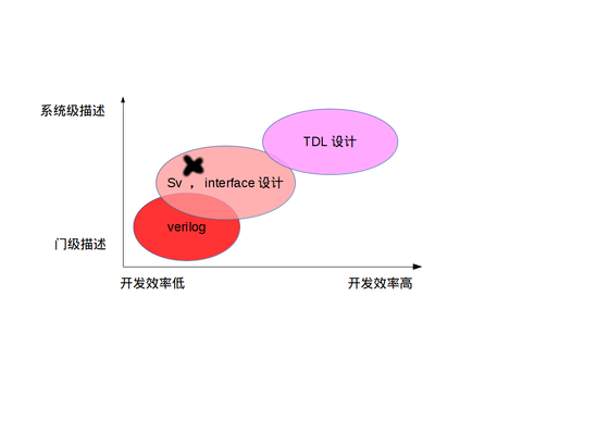
The above image provides a simple comparison of different implementations. I am currently at position X in the diagram, indicating that I am heavily using interface design, with development efficiency on par with Verilog (which is related to the number of interface IPs I have been accumulating). Essentially, TDL is not a new concept; it is entirely built upon interfaces, similar to how ARM SOC is built on AXI4. Without SystemVerilog (SV) interfaces, there would be no TDL. Transitioning from interfaces to TDL is a natural progression, and the syntax of TDL is almost entirely based on specific bus SV modules. I have now accumulated enough AXI modules (about four times the number of Xilinx AXI IPs), and while some modules are just a few lines of code, they are very useful for TDL.
Time flies; from when I started using interfaces extensively in design (while writing “Where is FPGA Going”) to now, it has only been half a year, and I have already begun constructing the implementation environment for TDL, which I expect to complete this year.
The core of TDL is the automatic instantiation of SV interfaces and related modules, ultimately generating an SV file. When specific buses (AXI, AVALON, or others) are widely used in FPGA designs, and when modules that reuse these buses are abundant, using scripts to automatically generate code significantly improves efficiency. Here arises a question: can all our design challenges be addressed solely using specific interfaces (like AXI)? My answer is yes; not only can it be done, but designs should only follow standard buses. After all, think about it: FPGA SOCs only adopt one bus.
“How We Get to Now” makes a valid point; the timing is just right. ModelSim only started to effectively support the hierarchical reference of SV interface syntax parameters in its latest version (10.5, released last year; version 10.4 did not support it). Vivado has also only recently made SV synthesis barely usable in the last two versions, although there are many areas needing optimization. Therefore, even a year ago, attempting to use interface interconnect designs extensively in FPGA would have been frustrating, as you would face a slew of software bugs. “How We Get to Now” also suggests that I am not alone in thinking of the TDL concept.
—————————————————————————————————————————————–
Design should inherently target timing and be object-oriented, allowing for continuous integration, easy expansion, testing, and modification.
The above statement is what I wrote on the page; the following is the actual point.
Achieve the most functionality with the least code
Alright, let’s get to the main content. We will reconstruct a hardware design ecosystem, the Timing Description Language. The timing types used include classes like clock, video, AXI, AVALON, etc.
Starting from the basics, the simplest timing is the clock. The properties of the clock object are defined by its period; thus, we can have such syntax (I borrowed from Ruby).
clock_obj = Clock.new(freq:"100M")This is the simplest definition. Next, we have the methods of the Clock class, which includes a method for frequency division.
div2_clock = clock_obj.div(2)Now, although this differs greatly from traditional HDL, it may not yet be clear how productivity is enhanced. No worries; let’s discuss something more complex: the Video class.
v0 = Video.new(1080)    # Define a 1080P RGB timing
v1 = Video.new(1080)    # Define another 1080P RGB timing
We treat the image processing modules as methods of the object: low-pass filtering, high-pass filtering, edge sharpening, median filtering.
v_lpf = v0.LPF    # Perform low-pass filtering on image 0, using default parameters
v_hpf= v1.HPF   # Perform high-pass filtering on image 1, using default parameters
If the class does not have the method we want, for example, if the Video class lacks the median filter, we can define one ourselves.
def Video.medium_filter    # As long as the medium filter HDL file exists and the port definitions meet Video's requirements
end
Then we can use it like this:
v0_mf = v_lpf.medium_filter
v1_mf = v_hpf.medium_filter
Finally, we perform an alpha blend with 35% opacity:
v_out = v0_mf.alpha(v1_mf,0.35)The timing objects above are essentially intermediate variables and can completely compress the whole functionality into one line:
v_out = Video.new(1080) .LPF.medium_filter.alpha(Video.new(1080) .LPF.medium_filter,0.35)Thus, the code for overlaying two 1080 video streams after filtering is just the line above. It can be seen that it has specifically “strengthened” signal timing (like SV interfaces) and “weakened” the modules. Traditional designs simply associate groups of signal timings with a few related regs in Verilog; SV interfaces, and Qsys with varying connection widths, now transform into tangible class objects, each with their specific methods corresponding to modules, yet without the cumbersome port inout names, retaining only core functionalities.
————————————————————————————————————————
To further clarify, let’s assume we are doing a real simple project: stitching four 1080P streams into 4K, which may require some AXI knowledge.
And let’s assume we have the following basic modules (some of which correspond to real IPs from manufacturers):
DDR3 IP AXI4 interface
video_to_AXI_STREAM
AXI_STREAM_to_video
AXI_STREAM_to_AXI4_WR # This one does not exist in Xilinx; it converts AXI stream to AXI4 based on our definitions, essentially appending addr + len to the stream
AXI4_RD_to_AXI_STREAM # This simply removes all signals except for the stream
AXI4_packet_fifo
AXI4_burst_partition # This does not seem to exist in Xilinx; it partitions bursts into smaller chunks
AXI4_datawidth_convert # Converts data width
Now, here is the TDL CODE:
wr_origin_1080P[3:0] = Video.new()[3:0]    # Directly instantiate four 1080P raw timings
wr_orgin_axis[3:0]  =  wr_origin_1080P[3:0].video_to_AXI_STREAM  # Convert video stream to AXI stream
wr_orgin_axi4[0] = wr_orgin_axis[0].AXI_STREAM_to_AXI4_WR(addr:0)  # Write to address 0
wr_orgin_axi4[1] = wr_orgin_axis[1].AXI_STREAM_to_AXI4_WR(addr:100)  # Write to address 100
wr_orgin_axi4[2] = wr_orgin_axis[2].AXI_STREAM_to_AXI4_WR(addr:200)  # Write to address 200
wr_orgin_axi4[3] = wr_orgin_axis[3].AXI_STREAM_to_AXI4_WR(addr:300)  # Write to address 300

wr_par_axi4[3:0]    = wr_orgin_axi4[3:0].AXI4_datawidth_convert( 256  ) # Convert to 256-bit wide bus
wr_pkt_axi4[3:0]    = wr_par_axi4[3:0].AXI4_packet_fifo(4)    # FIFO depth of 4, indicating it can store 4 packets; DDR multi-read/write arbitration must have FIFO to store data
wr_pkt_axi4[3:0].DDR3_IP_AXI4() # Directly call DDR3 IP method, completely hiding arbitration interconnect

rd_pkt_axi4[3:0] = AXI4.new(4)[3:0]    # Directly instantiate four AXI4 interfaces
DDR3_IP_AXI4(rd_pkt_axi4[3:0] , [0,100,200,300])    # Read AXI4 from DDR3 IP
rd_axi_stream[3:0] = rd_pkt_axi4[3:0].AXI4_RD_to_AXI_STREAM   # Convert AXI4 to AXI stream
rd_video_1080p[3:0] = rd_axi_stream[3:0].AXI_STREAM_to_video  # Convert AXI stream to video
K4_sync(rd_video_1080p[3:0])     # Generate control signals for 4K resolution timing
The above functionality is basically complete….
To be continued
Let me mention one point: interfaces in Verilog can achieve a 3-5 times efficiency improvement, TDL for SV interfaces can achieve around a 10 times improvement, and TDL for traditional Verilog can achieve 30-50 times efficiency.
What does this mean? During the A7 200T period, 1000 lines of code could fully utilize the resources.
I rarely declare copyright, but this article is extremely important and must include a copyright statement.
Copyright Statement:
This article was published by the blogger “Wu Ming”. Reproduction is welcome, but the content of the blog must not be altered, nor used for any profit-making purposes. When reproducing, do not delete the author’s profile and copyright statement. Any copyright disputes arising from unauthorized use without attribution shall be the responsibility of the infringer.