The failure caused by capacitor damage is the highest in electronic devices, especially with the failure of electrolytic capacitors being the most common. Capacitor damage manifests as: reduced capacity, complete loss of capacity, leakage, and short circuit.Capacitors play various roles in circuits, and the faults they cause are also characterized differently: in industrial control circuit boards, digital circuits account for the vast majority, and capacitors are mostly used for power filtering, with fewer used for signal coupling and oscillation circuits. If the electrolytic capacitor used in the switch power supply is damaged, the switch power supply may not oscillate, resulting in no voltage output;or the output voltage may not be filtered well, causing the circuit to experience logical confusion due to unstable voltage, resulting in the machine working intermittently or failing to start. If the capacitor is placed between the positive and negative terminals of the power supply in the digital circuit, the fault manifests similarly.This is particularly evident on computer motherboards; many computers show symptoms of sometimes failing to start after a few years of use. Upon opening the case, one often sees bulging electrolytic capacitors. If you remove the capacitor and measure its capacity, it is found to be significantly lower than the actual value.The lifespan of a capacitor is directly related to the ambient temperature; the higher the ambient temperature, the shorter the capacitor’s lifespan. This rule applies not only to electrolytic capacitors but also to other capacitors. Therefore, when searching for faulty capacitors, one should focus on capacitors that are relatively close to heat sources, such as those near heat sinks and high-power components; the closer they are, the greater the likelihood of damage. Thus, during maintenance and troubleshooting, one should prioritize these checks.Some capacitors may leak significantly, and touching them can even feel hot; such capacitors must be replaced. During troubleshooting for intermittent faults, if the possibility of poor contact is ruled out, the majority of faults are generally caused by capacitor damage. Therefore, when encountering such faults, it is advisable to focus on inspecting the capacitors, and replacing them often yields surprising results.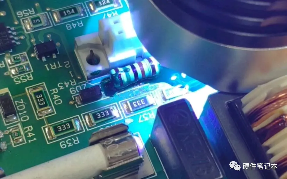 Resistor FaultsMany beginners often struggle with resistors during circuit repairs, disassembling and soldering them repeatedly. However, with experience, once you understand the characteristics of resistor damage, you won’t need to go through so much trouble.Resistors are the most numerous components in electrical devices, but they are not the components with the highest failure rate. Resistor damage is most commonly an open circuit, while an increase in resistance is less common, and a decrease in resistance is very rare. Common types include carbon film resistors, metal film resistors, wire-wound resistors, and fusible resistors.The first two types of resistors are widely used, and their damage characteristics are as follows: low resistance (below 100Ω) and high resistance (above 100kΩ) have a higher failure rate, while mid-range resistance (such as hundreds of ohms to tens of kilohms) rarely fails; low resistance resistors often show signs of burning and blackening when damaged, making them easy to identify, while high resistance resistors rarely show any signs of damage.Wire-wound resistors are generally used for current limiting and have low resistance values; cylindrical wire-wound resistors may show blackening or surface peeling and cracking when burnt, while some show no signs; cement resistors, a type of wire-wound resistor, may break when burnt, otherwise showing no visible signs; fusible resistors may have their surfaces blown off or show no signs, but will never be burnt black. Based on these characteristics, when checking resistors, one can prioritize finding the damaged ones quickly.Based on the characteristics listed above, we can first observe whether there are any signs of burning on low resistance resistors on the circuit board, and then based on the fact that most resistor failures are open circuits or increased resistance, and that high resistance resistors are prone to failure, we can use a multimeter to directly measure the resistance across the high resistance resistors on the circuit board.If the measured resistance is greater than the nominal resistance, then this resistor is definitely damaged (note that the resistance must stabilize before drawing a conclusion, as there may be parallel capacitive components in the circuit that cause a charging and discharging process); if the measured resistance is less than the nominal resistance, it is generally not a concern. By measuring each resistor on the circuit board in this way, even if a thousand are “wrongly killed,” none will be overlooked.Operational Amplifier FaultsDetermining the quality of an operational amplifier can be quite challenging for many electronic repair technicians, not only due to educational background but also due to practical knowledge. Here, I would like to discuss this with everyone in the hope of being helpful.An ideal operational amplifier has the characteristics of “virtual short” and “virtual open,” which are very useful for analyzing linear applications of operational amplifier circuits. To ensure linear operation, the operational amplifier must operate under closed-loop (negative feedback). If there is no negative feedback, the open-loop amplifier becomes a comparator. To determine whether the device is good or bad, one must first clarify whether the device is used as an amplifier or as a comparator in the circuit.According to the principle of the virtual short of the amplifier, if this operational amplifier is working normally, the voltages at its inverting and non-inverting input terminals must be equal, even if there is a difference, it should only be in the millivolt range. Of course, in some high input impedance circuits, the internal resistance of the multimeter may slightly affect the voltage measurement, but it generally does not exceed 0.2V. If there is a difference of more than 0.5V, then the amplifier must be faulty.If the device is used as a comparator, then the voltages at the inverting and non-inverting input terminals are allowed to be unequal. If the non-inverting voltage > inverting voltage, then the output voltage approaches the positive maximum value; if the non-inverting voltage < inverting voltage, then the output voltage approaches 0V or the negative maximum value (depending on whether it is dual-supply or single-supply). If the detected voltage does not conform to these rules, then the device must be faulty! Thus, you do not need to use substitution methods or remove the chip from the circuit board to judge the operational amplifier’s quality.
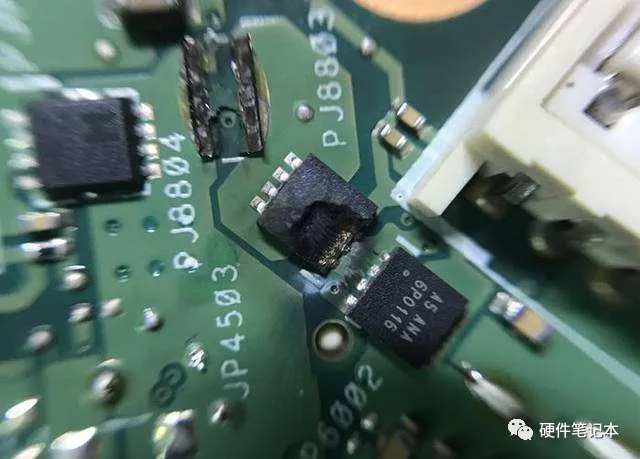 SMT Component FaultsSome surface mount components are very small, making it inconvenient to test and repair them with ordinary multimeter probes. First, they can easily cause short circuits; second, it is difficult to contact the metal parts of the component leads on circuit boards coated with insulating layers. Here, I will share a simple method that will greatly facilitate testing.Take two of the smallest sewing needles, press them against the multimeter probes, and then take a thin copper wire from a multi-stranded cable, tie the probes and needles together with the thin copper wire, and solder them securely. This way, when using the probe with small needle tips to measure those SMT components, there is no risk of short circuits, and the needle tips can pierce through the insulating coating to reach critical areas without the need to scrape off the coatings.Common Power Supply Short Circuit FaultsIn circuit board repairs, encountering common power supply short circuit faults can often be daunting, as many components share the same power supply, and each component using this power supply may be suspected of short-circuiting.If there are not many components on the board, using a “ground-clearing” method can eventually help find the short circuit point; if there are too many components, relying on luck may determine whether the “ground-clearing” method can locate the situation. Here, I recommend a more effective method that can often quickly locate the fault point.You will need a power supply that can adjust both voltage and current, with a voltage range of 0-30V and a current range of 0-3A. This type of power supply is inexpensive, costing around 300 yuan. Set the open-circuit voltage to the level of the device’s power supply voltage, first adjusting the current to the minimum, and then applying this voltage to the power supply voltage points of the circuit, such as the 5V and 0V terminals of the 74 series chips, gradually increasing the current based on the degree of short circuit.Touch the components with your hand; when you feel a particular component getting significantly hot, that is often the damaged component, which can then be removed for further measurement and confirmation. Of course, during operation, the voltage must not exceed the device’s working voltage, and it must not be connected in reverse, or other good components may get damaged.
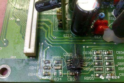 Board Card FaultsIndustrial control uses more and more board cards, many of which use gold fingers inserted into slots. Due to the harsh environment of industrial sites, which are dusty, humid, and full of corrosive gases, board cards are prone to contact faults. Many friends may have solved the problem by replacing the board cards, but the cost of purchasing board cards can be significant, especially for certain imported equipment.In fact, everyone might try using an eraser to rub the gold fingers a few times, cleaning off the dirt on the gold fingers, and then test the machine again; this simple and practical method may just solve the problem.Electrical FaultsVarious intermittent electrical faults can be categorized based on their probability as follows:
- Poor contact: Poor contact between the board card and slot, intermittent breaks in internal cables, poor contact at connectors and terminal blocks, and cold solder joints are all included in this category;
- Signal interference: For digital circuits, faults may only present under specific conditions; it is possible that interference is too strong, affecting the control system and causing errors, or that individual component parameters or overall performance parameters of the circuit board have changed, causing the anti-interference ability to approach critical points, thus leading to faults;
- Poor thermal stability of components: Based on extensive repair experience, the thermal stability of electrolytic capacitors is the worst, followed by other capacitors, transistors, diodes, ICs, and resistors;
- Moisture and dust on the circuit board: Moisture and accumulated dust can conduct electricity and have a resistance effect, and during thermal expansion and contraction, the resistance may change. This resistance may have a parallel effect with other components, and when this effect is strong, it may change the circuit parameters and cause faults;
- Software is also a consideration: Many parameters in the circuit are adjusted using software, and if certain parameter tolerances are set too low, they may be in critical ranges. When the machine operates under conditions that meet the software’s criteria for fault detection, alarms will appear.
- Statement:All rights to this article belong to the original author and do not represent the views of the association. The articles promoted by the “Jiangxi Province Electronic Circuit Industry Association” are for sharing purposes only and do not represent the position of this account. If there are any copyright issues, please contact us for removal.
-