1
Introduction to RA0L1
The RA0L1 is a basic microcontroller (MCU) in the RA0 series, positioned as an entry-level product line, offering excellent cost-performance ratio and ultra-low power consumption characteristics. This product is designed based on the Arm Cortex-M23 core, with a CPU operating speed of up to 32MHz, and integrates 64KB of Code Flash and 16KB of SRAM, supporting a wide operating temperature range from -40°C to 125°C.
2
Applicable Scenarios for RA0L1
The RA0 series microcontrollers are designed for cost-sensitive applications, particularly suitable for the following fields:
-
Low power and low-cost requirements in consumer electronics
-
Control of small household appliances
-
Industrial system control
-
Building automation
3
Main Features of RA0L1
The main features are as follows:
-
32MHz Arm Cortex-M23 core;
-
Up to 64KB Flash (Code Flash): minimum erase unit of 2KB, minimum write unit of 4 bytes;
-
1KB Data Flash: minimum erase unit of 256 bytes, minimum write unit of 1 byte;
-
Operating temperature range: -40°C to +125°C;
-
Low power consumption: operating mode 2.9mA@32MHz, Standby mode: 0.25uA;
-
Wide voltage operation: supply voltage range from 1.6V to 5.5V;
-
±1% high-speed high-precision on-chip oscillator;
-
Cap Touch capacitive touch IP: CTSU2SLa;
-
TAU (16-bit general-purpose PWM timer), TML32 (32-bit interval timer), RTC (real-time clock);
-
Rich analog resources: 12-bit analog-to-digital converter (A/D Converter), temperature sensor;
-
SAU (integrated UART, simple SPI, simple I2C);
-
UARTA interface, I2C interface;
-
True random number generator;
-
Safety functions.
4
Supported Development Tools
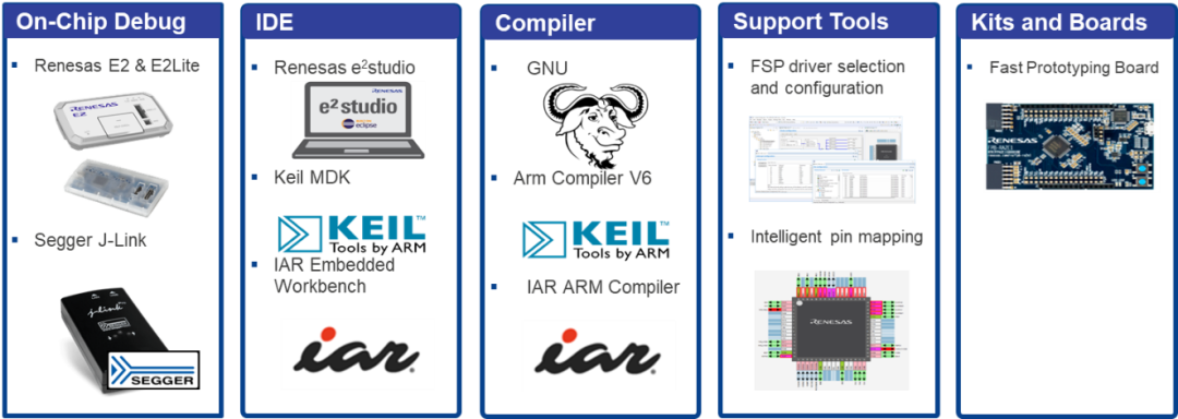
Please refer to the following content for download links for each tool.
Scan the QR code below or copy the link to view related information.
Swipe to view the full content
IDE
1
Name:e2 studio
Version/Download Link:
Renesas e2 studio downloads
https://www.renesas.cn/zh/software-tool/e-studio#downloads

2
Name:Keil MDK
Version/Download Link:
ARM Product Updates (keil.com)
https://www.keil.com/update/rvmdk.asp

3
Name:
IAR Embedded Workbench for Arm
Version/Download Link:
IAR EW for Arm Free Trial Version
https://www.iar.com/products/architectures/arm/iar-embedded-workbench-for-arm/iar-embedded-workbench-for-arm-free-trial-version/

Swipe left for more
ICE
1
Name:E2 & E2 Lite
Version/Download Link:
E2 emulator
[RTE0T00020KCE00000R] | Renesas
https://www.renesas.com/en/software-tool/e2-emulator-rte0t00020kce00000r

Version/Download Link:
E2 emulator Lite
[RTE0T0002LKCE00000R] | Renesas
https://www.renesas.com/en/software-tool/e2-emulator-lite-rte0t0002lkce00000r

2
Name:EZ-CUBE3
Version/Download Link:
EZ-CUBE3 | Renesas
https://www.renesas.cn/zh/software-tool/ez-cube3?queryID=d34a4fc6da0b927359e798d084f9d974

3
Name:J-Link
Version/Download Link:
Segger Debug Probes J-Link
https://www.segger.com/products/debug-probes/j-link/

4
Name:I-jet
Version/Download Link:
IAR I-jet
https://www.iar.com/products/architectures/arm/i-jet

Swipe left for more
Code Generator
1
Name:
RASC (RA Smart Configurator)
Documentation Version/Download Link:
RASC MDK IAR User Guide
https://renesas.github.io/fsp/_s_t_a_r_t__d_e_v.html#RASC-MDK-IAR-user-guide

2
Name:FSP
Version/Download Link:
Releases · renesas/fsp
https://github.com/renesas/fsp/releases/

Swipe left to return
For example code and development boards, please refer to the following content.
Scan the QR code below or copy the link to view related information.
RA Product Examples
Brief Description:Includes most examples for the RA series productsNote
Download Link:
RA Product Examples
https://github.com/renesas/ra-fsp-examples

Development Board
Brief Description:RFP board for the RA series
Download Link:
Renesas RA Microcontroller Evaluation Kits
https://www.renesas.com/en/products/microcontrollers-microprocessors/ra-cortex-m-mcus/ra-kits

Note:Examples for RA0L1 will be updated after the official release of RA0L1.
5
Getting to Know the RA0L1 Board
FPB-RA0L1
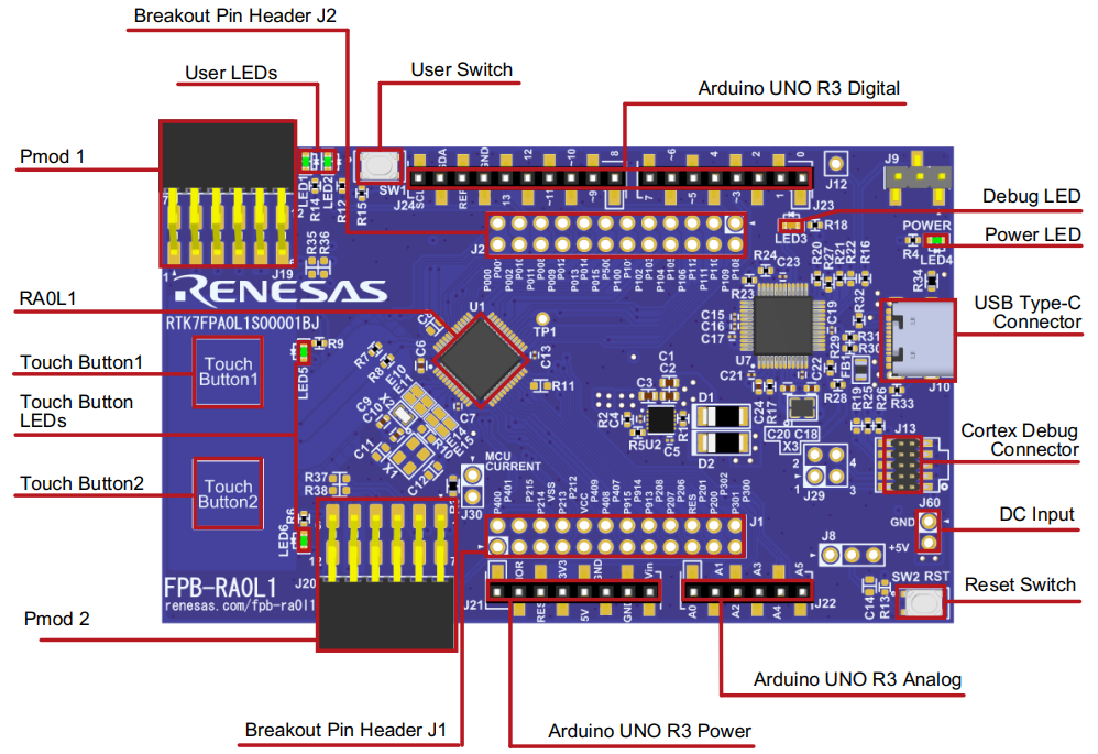
Top view of FPB-RA0L1
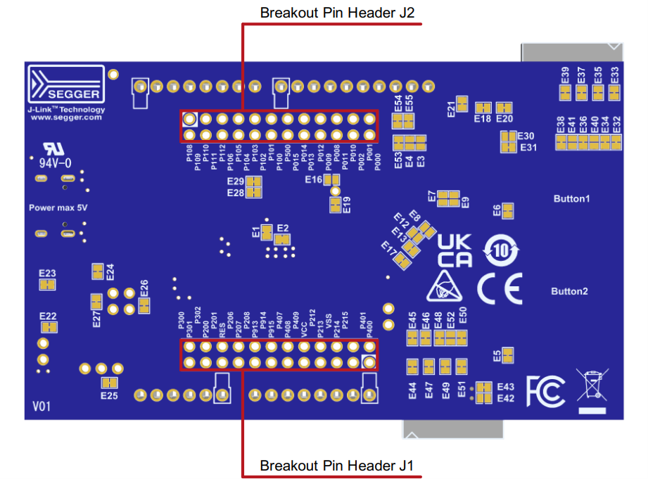
Bottom view of FPB-RA0L1
The FPB-RA0L1 development board is equipped with a power regulator, onboard debugger, simple input/output devices (Cap touch buttons and LEDs), and commonly used ecosystem input/output connectors. The following will provide detailed introductions to these.
Power Supply
-
The FPB-RA0L1 development board is designed to be powered by 5V. An onboard LDO converts the 5V supply to a 3.3V supply. The 3.3V supply powers the RA MCU and other peripheral functions. Power can be supplied via Debug USB (default setting) or J60.
-
The onboard regulator (LDO) providing 3.3V has a built-in current limit of 2.0A. Ensure that the total current required by the RA MCU and any connected peripherals does not exceed this limit.
-
Once powered on, the green LED4 labeled “POWER” will light up, and the yellow “DEBUG” LED3 will also light up.
Special Function Interfaces
-
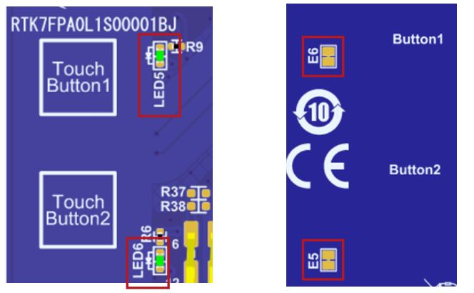
The FPB-RA0L1 provides two capacitive touch buttons.
The pin allocation for the capacitive touch buttons is shown in the table below.
|
Identifier |
RA MCU Control Port |
|
Touch Button1 |
P001/TS22 |
|
Touch Button2 |
P000/TS23 |
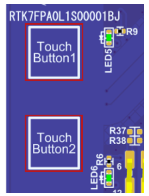
Top view of Cap Touch Button
Jumpers related to Cap Touch Button
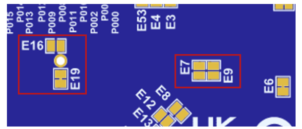
If you want to use P001 for GPIO functionality, jumper E7 needs to be shorted.
If you want to use P000 for GPIO functionality, jumper E9 needs to be shorted.
P112 is defaulted for TSCAP and is connected to a 10nF capacitor. If you want to use P112 for GPIO, E16 must be shorted while E19 must be disconnected.
-
Touch Button LEDs
The RFP-RA0L1 provides two touch button LEDs near the touch buttons to indicate these buttons.
|
Identifier |
Color |
RA MCU Control Pin |
|
LED5 |
Green |
P401 (lights up at low level) |
|
LED6 |
Green |
P400 (lights up at low level) |
In addition to serving as indicators for the touch buttons, the ports controlling the touch button LEDs can also be used for any required purpose. The LEDs can also be isolated from the RA MCU so that the related ports can be used for other purposes. To disconnect LED5 from P401, E6 must be disconnected. To disconnect LED6 from P400, E5 must be disconnected.
Top view
Bottom view
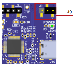
Debugging
The FPB-RA0L1 development board can be programmed and debugged using the built-in SEGGER J-Link® onboard debugger. The onboard debugging functionality is provided by Renesas RA4M2 (J-Link OB) and SEGGER J-Link®. The USB 2.0 Type-C™ connector (J10) for debugging connects the RA4M2 (J-Link OB) to an external PC for reprogramming and debugging the firmware of the target RA MCU. This connection method is the default debugging mode for the FPB-RA0L1 development board.
|
Debug Mode |
J9 |
|
On-Board |
1-2 |
|
Debug In |
2-3 |
Click to view the large image
6
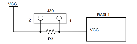
MCU Power Measurement
There is a resistor R3 and a test connector J30 (not soldered) near the RA0L1 for measuring MCU current. The resistor R3 is 0Ω (0603 package) at the factory. To measure the current using an ammeter connected between pins 1 and 2 of J30 (not soldered), the resistor R3 should be removed.
Alternatively, you can remove resistor R3 and replace it with a suitable low-resistance resistor (e.g., 100mΩ), and then use a voltmeter to measure the voltage between pins 1 and 2 of J30. You can then use Ohm’s law to calculate the current consumed by the MCU.
Current measurement schematic
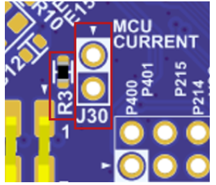
J30 current measurement point
7
Conclusion
The RA0L1 is a recently launched entry-level MCU from Renesas, featuring capacitive touch, low power consumption, and rich peripherals. It supports various development tools, and example code is easily available online, with onboard debugging capabilities that allow users to get started without additional debugging tools.

Need Technical Support?
If you have any questions while using Renesas MCU/MPU products, you can identify the QR code below or copy the URL into your browser to enter theRenesas Technical Forum to find answers or get online technical support.

https://community-ja.renesas.com/zh/forums-groups/mcu-mpu/
1
END
1
Recommended Reading

Renesas Electronics RA ultra-low power MCU new product RA0L1, developed for capacitive touch applications

Let AI Happen | 2025 Renesas Edge AI Technology Seminar Kicks Off

Q&A Win Prizes | 5 min to understand Renesas CTSU2 touch button and slider waterproof solutions