– Create a STEP 7 project – Insert the required SIMATIC S7-1200 station – Insert the communication module and other required modules in the station – Add the PROFIBUS DP network, assign DP addresses, define operating modes and DP parameters
-
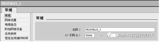
DP Address Definition
-
DP Master/Slave Mode Selection
-
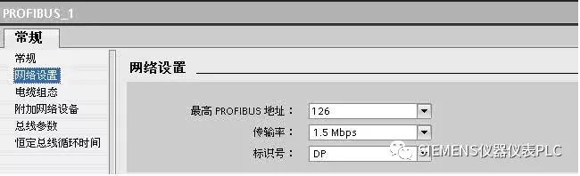
Maximum Address: Since the PROFIBUS token is only passed to the master station, an appropriate maximum PROFIBUS address can optimize the bus
– Connect the DP slave to the master station – Configure other modules – Save and download the project
1. General Configuration Method for DP Slaves:
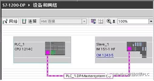
Taking S7-1200 and ET200S as an example, the configuration process is explained. (1) S7-1200 acts as the DP master station through CM1243-5
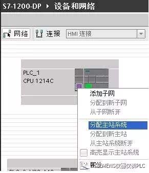
(2) Create a DP master system by right-clicking the DP interface of the CM1243-5 master station module in the network view, and select “Assign Master System” to create the DP master station.
(3) Drag ET200S from the hardware catalog/distributed I/O into the network view, drag the slave communication interface to the master station interface, and release the mouse button to create the PROFIBUS connection.
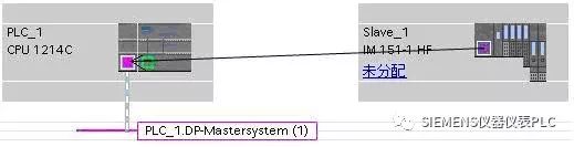
Click on “Unassigned” on the ET200S to assign it to CM1243-5. The display is as shown below
Right-click on the network cable to view network parameters, where you can modify transmission rate, maximum station address, etc.
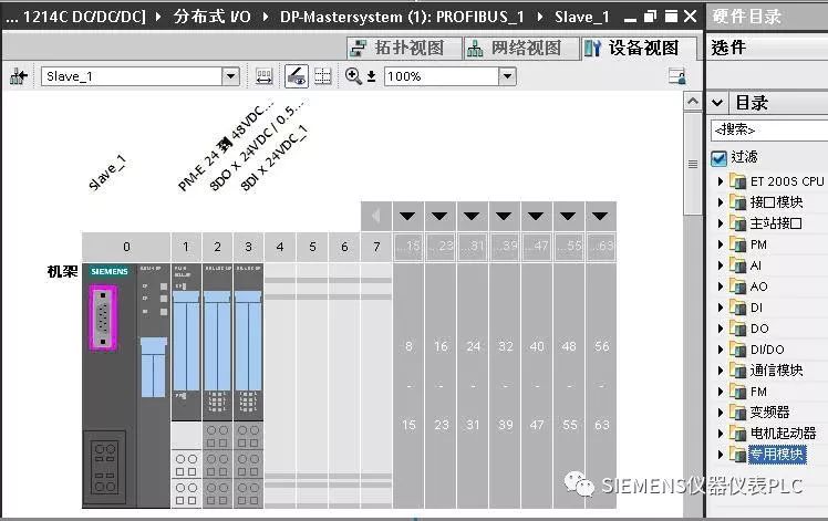
(4) Double-click ET200S to configure other modules such as the power module PM-E, DO module, and DI module as shown in the figure.
(5) Compile, save, and download to the S7-1200 CPU
2. Smart Slave Configuration Method
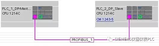
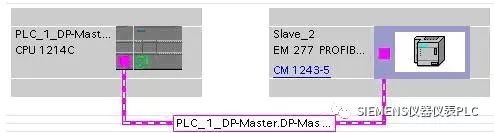
Taking two S7-1200 DP communication configurations as an example. (1) PLC_1_DP_Master acts as the PROFIBUS DP master station through CM1243-5, while PLC_2_DP_Slave acts as the PROFIBUS DP slave through CM1242-5. Configure the devices and create the DP master network
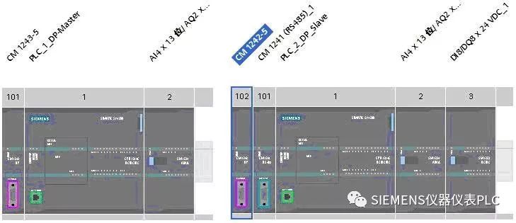
(2) Connect the slave to the master station, assigning PLC_2_DP_Slave to the DP master CM1243-5
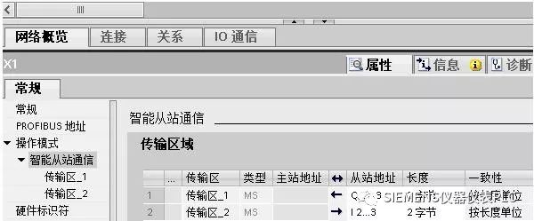
(3) Double-click PLC_2_DP_Slave, click on the DP port to configure the data transfer area through properties
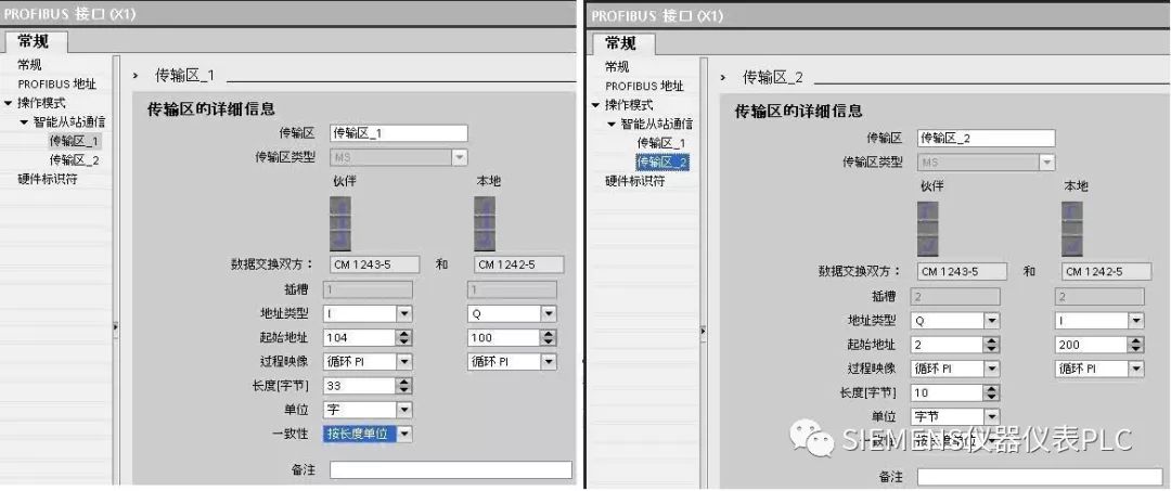
In transfer area_1, the master station reads 33 words from the slave, while transfer area_2 sends 10 bytes to the slave, maintaining data consistency by length unit. “By length unit” consistency data reading does not require writing communication programs.
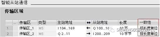
For example, in transfer area_1, the master station reads 33 words starting from slave QW100 into the address starting from IW104. Compile, save, and download the program to their respective CPUs. The data correspondence can be seen through the monitoring table.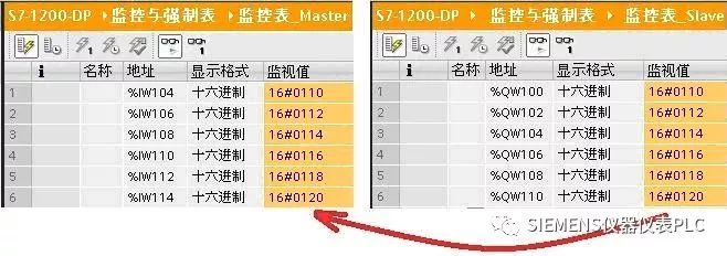
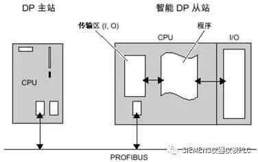
For the I/O modules of smart slaves: The DP master station cannot directly read and write the I/O modules of smart slaves. It must write a program through the smart slave CPU to exchange data between the I/O modules and the DP transfer area.
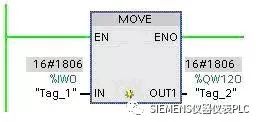
If the master station wants to read the integrated input point IW0 of the slave CPU, a MOVE program needs to be inserted into the main loop program OB1 of the slave, as shown in the figure, using the MOVE instruction to transfer IW0 to QW120. Using the above configuration, the slave data QW120 reaches the master station’s IW124 through transfer area_1.
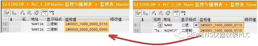
Through the monitoring table shown in the figure, it can be seen that the master station reads the integrated point IW0 of the slave CPU in IW124.
3. Configuration Based on GSD for DP Slaves
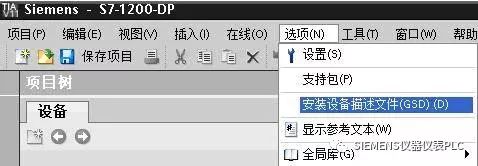
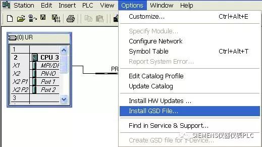
When the DP slave is a third-party device or a Siemens device not found in the STEP7 V11 hardware list, the device can be added to STEP7 V11 by installing the GSD file provided by the device supplier. Below is the configuration process using S7-1200 as the master through CM1243-5 and S7-200 as the slave through EM277: (1) Install the EM277 GSD file in STEP7 V11. Before installing the GSD file, close the hardware and network editor, and select “Install Device Description File” from the “Options” menu.
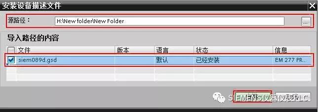
Select the folder containing the GSD file from the “Source Path”, choose the file to install from the displayed GSD file list, and click the “Install” button.
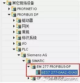
After restarting STEP7, the DP slave installed via the GSD file can be found in the “Other Field Devices” folder in the hardware catalog.
(2) Drag and drop EM277 into the network view and connect it to the master module CM1243-5
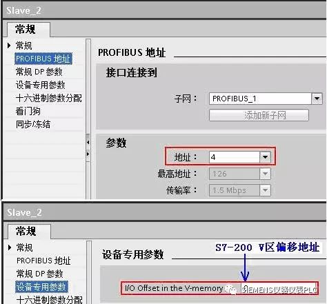
(3) Double-click EM277 to view the PROFIBUS DP parameters in the properties. The EM277 DP address is 4, and the V area address offset is 0
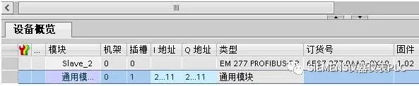
(4) Configure communication data. The EM277 device overview has only one configurable slot. Depending on the communication data requirements, you can choose fixed message or generic module. In this case, the generic module is selected, defining data exchange with the master station as 10 bytes input and 10 bytes output, with consistency selected as “by length unit”.
(5) Compile and check the configuration, download to the S7-1200 CPU.
(6) Set the EM277 address dip switch to 4, and start the PLC.
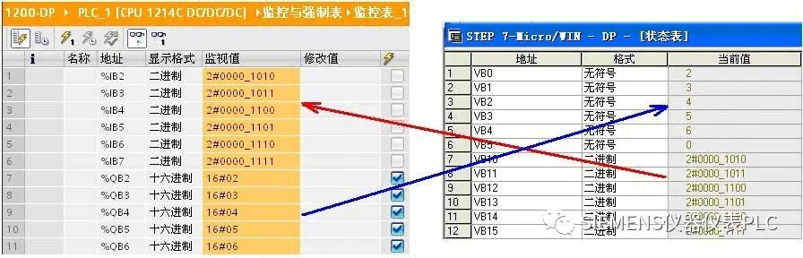
Check communication data through the monitoring table of S7-1200 and the status table of S7-200.
4. Master and Slave Not in the Same Project
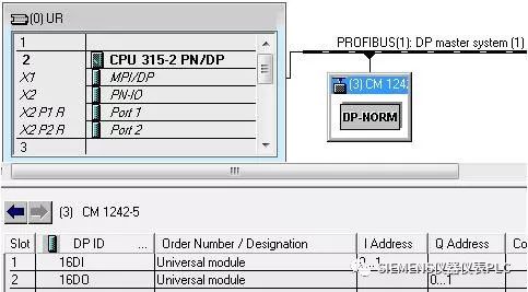
When the DP master station and DP slave are not in the same project, the DP communication configuration must be completed in their respective projects. As in the following example, CPU315-2PN/DP acts as the DP master station, while CPU1214C and CM1242-5 act as the DP smart slave. The configuration for CPU315-2PN/DP is completed in STEP7 V5.5, while S7-1200 uses STEP7 V11 SP2 for configuration. (1) Configure the DP master station in STEP7 V5.5 a. Install the CM1242-5 GSD file in STEP7 V5.5
 CM1242-5 GSD File Local Download In STEP7 V5.5 hardware configuration, Option/Install GSD File, install the CM1242-5 GSD file into STEP7 V5.5.
b. Connect the DP slave module CM1242-5 with address 3 to CPU315-2PN/DP. Insert a generic module with 2 bytes of input into slot 1; insert a generic module with 2 bytes of output into slot 2.
c. Download the DP master station configuration as compiled and checked above. If there are no errors, save and download to CPU315-2PN/DP.
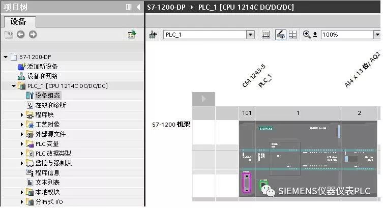
(2) Configure the DP slave in STEP7 V11 a. In STEP7 V11, add the PLC station S7-1200 and the CM1242-5 module in the STEP7 V11 project view. The DP port of the CM1242-5 module adds a new network PROFBUS_1, defining the DP address as 3, the same as in STEP7 V5.5. Since the master station is not in the same project, the master allocation status of S7-1200 is “Unassigned”.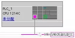
b. Configure communication transfer area by selecting the DP port property on the CM1242-5 module and adding the data transfer area for communication with the master station. Insert 2 bytes of output into slot 1, and insert 2 bytes of input into slot 2, crossing the correspondence with the master station communication configuration slots.
c. Download to the CPU of S7-1200 by selecting the S7-1200 PLC station, compile, and if there are no errors, download the configuration to CPU 1214C.
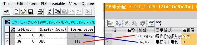
(3) Check communication status through the variable table of STEP7 V5.5 and the monitoring table of STEP7 V11 to view the DP communication results.