Working Principle and Function Introduction
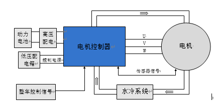
The controller, as a key power component in electric vehicles, interacts with the vehicle through the CAN network to exchange commands and status information. The controller collects motor current, speed, and position signals, integrates system status and vehicle control commands, and converts the DC power from the vehicle’s high-voltage distribution into AC power to drive the motor.
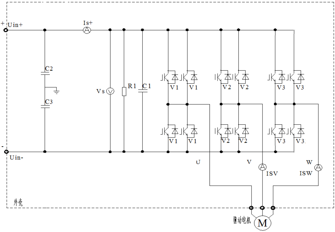
MCU Main Circuit Schematic
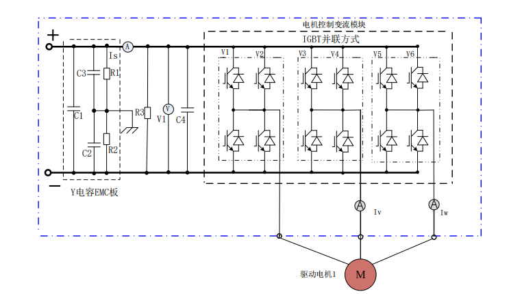
The main circuit of the controller is shown in the figure above. It consists of a DC current sensor Is, voltage acquisition circuit V1 (integrated on the control board), discharge resistor R3, support capacitor C4, motor controller conversion module V1 to V6, AC current sensors ISV and ISW, Y capacitors C2 to C3, X capacitor C1, intermediate resistors R1 to R2, and electrical connection lines and busbars.
Function Descriptions of Various Components and Circuits
Discharge Resistor
After the high-voltage DC power supply is disconnected, the discharge resistor releases the charge on the support capacitor to prevent electric shock. The DC support capacitor stabilizes the DC voltage and provides reactive power to the motor.
DC Current Sensor
Detects the value of the DC current flowing into the controller. The AC current sensor detects the current of the V and W phase lines of the motor.
Introduction to the Working Principle of the Cooling System
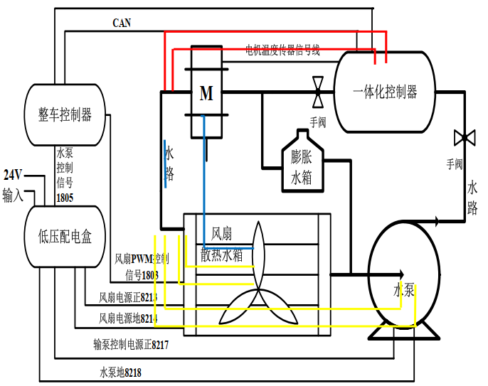
1. Water Pump Start/Stop Strategy:
The motor controller starts at 45°C and stops at 38°C; the drive motor starts at 85°C and stops at 70°C.
2. Fan Start/Stop Strategy:
The motor controller starts at 58°C and stops at 46°C; the drive motor starts at 95°C and stops at 85°C.
Fault Codes: 1641: Motor controller (limp mode) reaches reduced power temperature threshold of 75°C 1642: Motor controller (stop mode) reaches reduced power temperature threshold of 80°C 1644: Drive motor (limp mode) reaches reduced power temperature threshold of 135°C 1645: Drive motor (stop mode) reaches reduced power temperature threshold of 165°CTroubleshooting Ideas: 1. Insufficient coolant, wiring harness, connector faults 2. Water pump or fan not working, water pump performance degradation
3. Motor temperature sensor failure
4. Integrated controller failure
5. Residual air or debris blocking the water circulation channel
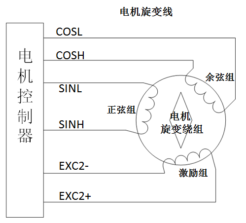
Working Principle:The motor controller connects to the motor’s resolver windings through a resolver line. First, the motor controller outputs a fixed sine waveform to the excitation winding of the resolver. The change in the motor rotor position affects the amplitude and phase of the cosine and sine groups. The resolver decoding chip decodes the sine and cosine waveforms to calculate the motor angle, position, speed, and other data; real-time monitoring and data transmission.
51: Resolver fault in the motor,
The motor controller detects a significant deviation in the initial positioning angle of the resolver (exceeding 15°)
99: Resolver fault, motor overspeed;
Troubleshooting Ideas: 1. Motor angle deviation; 2. Resolver winding fault; 3. Signal line misconnection; 4. Excitation line misconnection; 5. Motor body fault; 6. Program mismatch with the motorIntroduction to the Motor Temperature Sensor
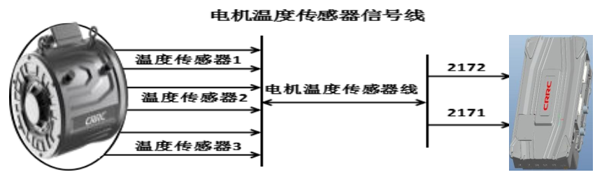
1679, 1680: Motor sensor fault, motor temperature sensor short circuit or open circuit fault
Troubleshooting: 1. Check if the motor sensor contact line is normal; 2. Check if the motor sensor resistance value is around 120Ω (NTC sensor resistance value should be around 10KΩ) 3. Check the integrated controller end, low-voltage harness X2 connector, for pin retraction
4. Check if the program matches the motor
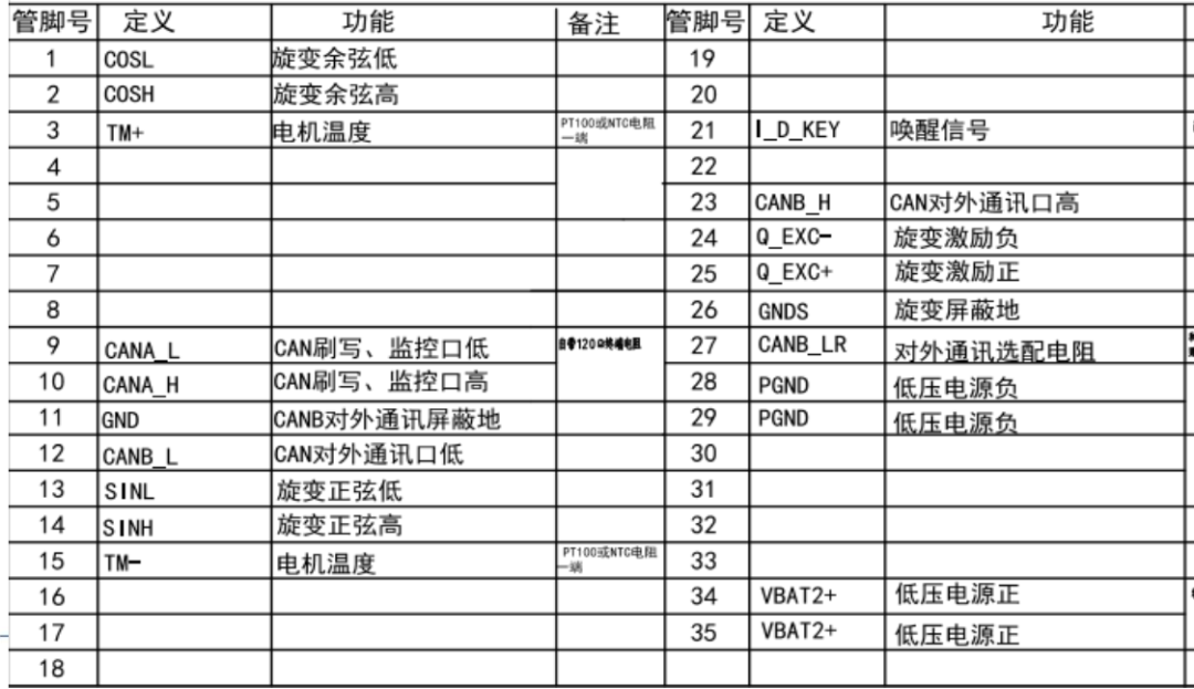
Control Logic and Pin Definitions
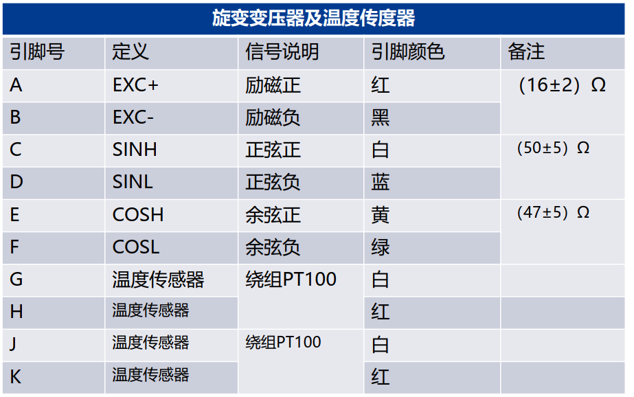
Motor Controller Signal Definitions
……To learn more about new energy knowledge, please subscribe to “New Energy Learning Circle”


About Truck Maintenance Academy
Truck Maintenance Academy is a high-tech service enterprise that provides skill training and technical services for the entire value chain of the commercial vehicle aftermarket. Our product range includes professional skill training, technical services, and digital training system solutions for commercial vehicle manufacturers, parts distributors, logistics fleets, vocational colleges, and other users. We adopt an Internet + commercial vehicle skill training technology service model, combining online and offline services to help users establish a commercial vehicle thinking model system.
 Scan to Follow Us
Learn cutting-edge technology at Truck Maintenance Academy
Disclaimer: The content of this article is sourced from the internet. Please contact the author for removal in case of infringement.