
Before we start the article, let’s test everyone~
How many of the following five circuit diagrams can you understand?
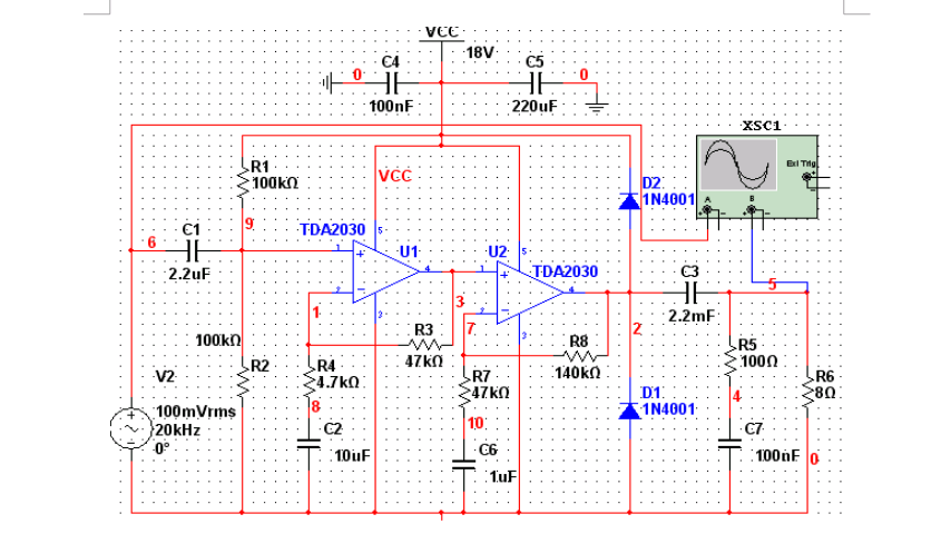
TDA2030 Circuit Diagram
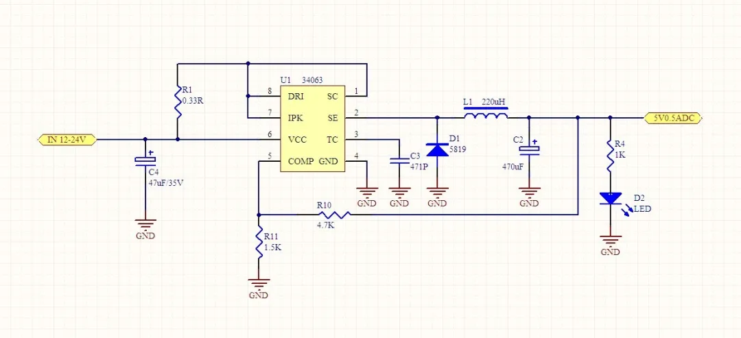
34063 Circuit Diagram
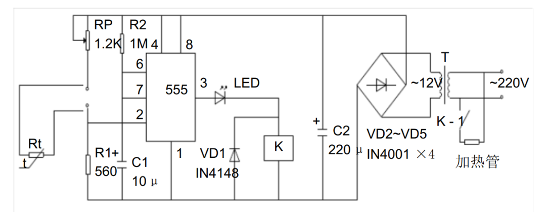
555 Circuit
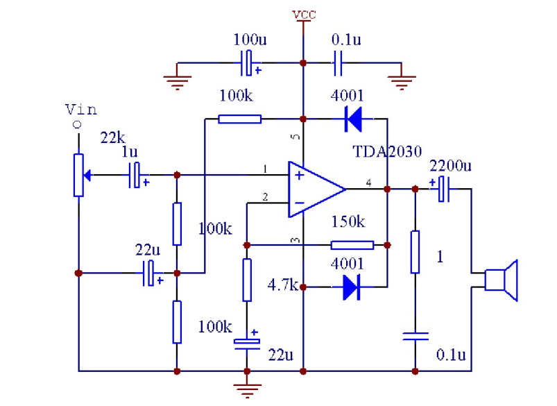
TDA2030 Circuit Diagram
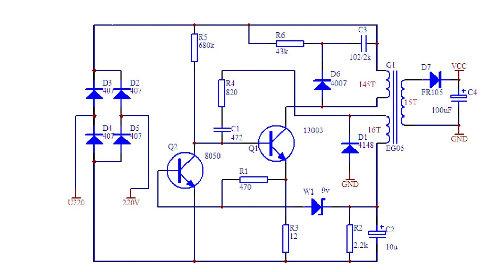
Transistor Discrete Component Circuit

If you can understand these circuit diagrams, you have already entered the field of electronic design. If not, let’s start learning these basic module circuits.
01.
Power Supply Circuit
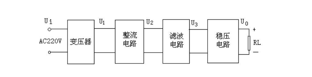
The DC voltage regulator is the power circuit for electronic devices, which relates to the stability and reliability of the entire circuit design. This section focuses on typical circuit designs composed of three-terminal fixed (positive and negative voltage) integrated voltage regulators, three-terminal adjustable (positive and negative voltage) integrated voltage regulators, and DC-DC circuits. Recommended related video:Foreigners teach you DC-DC, make a switch power supply.
Power Processing Block Diagram
The function of the rectifier circuit is to convert the AC voltage U1 into pulsating DC U2. It mainly has half-wave and full-wave rectification methods, which can be executed by a rectifier diode forming a rectifier bridge. Common rectifier diodes include IN4007, IN5148, etc., and bridge stacks include RS210, etc. The function of the filter circuit is to filter out the ripple from the pulsating DC U2, turning it into a low-ripple U3. Common circuits include RC filtering, KL filtering, and π-type filtering, with RC filtering being the most commonly used.
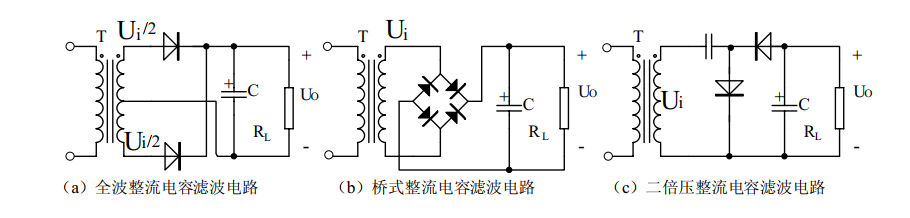
Centralized Rectification Form
In practical application circuits, in addition to connecting large-capacity filter capacitors between the chip’s input and output terminals and ground, it is usually necessary to connect small-capacity (0.1µF to 10µF) capacitors Ci and Co to ground at the root of the chip’s lead. Ci is used to suppress the chip’s self-oscillation, while Co is used to narrow the chip’s high-frequency bandwidth and reduce high-frequency noise. The specific values of Ci and Co should vary according to the chip’s output voltage and the application circuit.

Basic Application Circuit of 78 Series Three-Terminal Voltage Regulator
02.
Operational Amplifier Circuit
Operational amplifiers can generally be divided into several types: general-purpose, precision, low-noise, high-speed, low-voltage low-power, and single-supply types. Recommended related video:Understanding the principles of operational amplifiers.
Parameters that represent the performance of operational amplifiers include: single/dual power supply operating voltage, supply current, input offset voltage, input offset current, input resistance, conversion rate, differential input resistance, offset current temperature drift, input bias current, bias current temperature drift, differential voltage gain, common-mode voltage gain, unity-gain bandwidth, power supply voltage rejection, differential input voltage range, common-mode input voltage range, input noise voltage, input noise current, offset voltage temperature drift, settling time, long-term drift, etc.
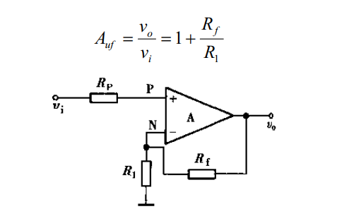
Inverting Input Proportional Operational Circuit
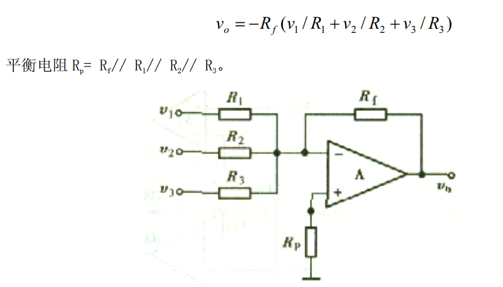
Inverting Input Proportional Summing Circuit
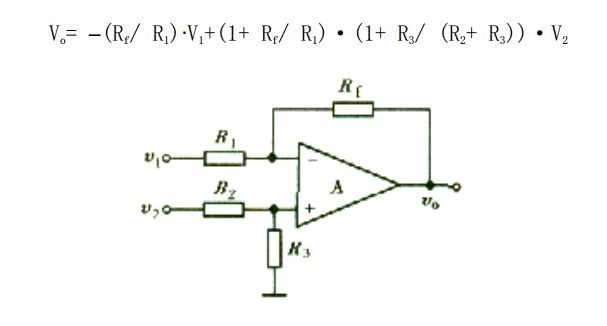
Differential Amplifier Circuit
03.
Signal Generation Circuit
In various electronic design processes, it is necessary to generate various waveforms, such as square waves, sine waves, triangular waves, single pulse waves, etc. The generation methods mainly utilize operational amplifiers or dedicated analog integrated circuits, along with a small number of external components to form various types of signal generators.
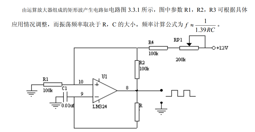
Discrete Analog Circuit for Generating Square Waves
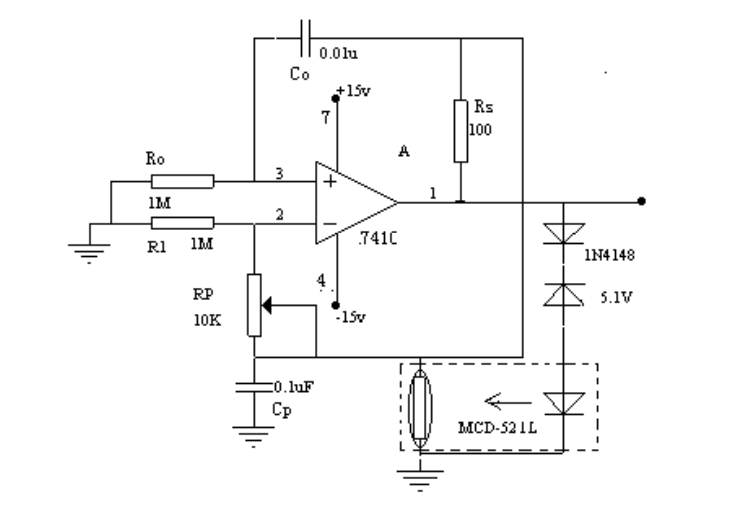
Self-oscillating Equivalent Inductor Oscillator
04.
Signal Processing Circuit
Signal processing circuits mainly utilize integrated operational amplifiers or dedicated analog integrated circuits, along with a small number of external components to form various functional processing circuits. The main functions include signal amplification, signal filtering, impedance matching, level shifting, nonlinear compensation, current/voltage conversion, voltage/frequency conversion, etc.
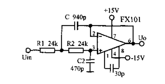
Active Low-pass Filter Composed of Operational Amplifiers
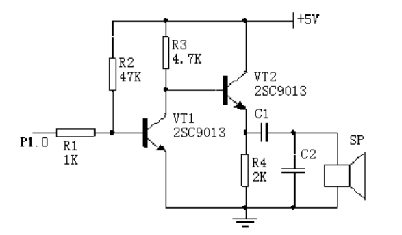
Sound Alarm Circuit
05.
Sensors and Their Application Circuits
Sensors are devices that can sense (or respond to) specified measured physical quantities and convert them into usable signal outputs according to certain rules. Sensors typically consist of sensitive elements that directly respond to the measured quantity, conversion elements that generate usable signal outputs, and corresponding electronic circuits.
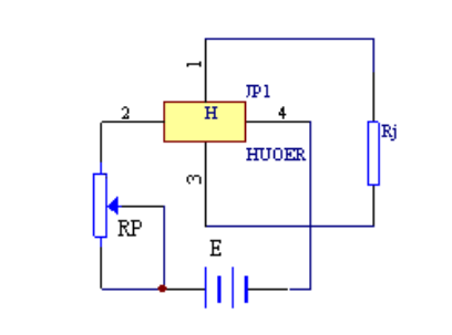
Basic Application of Hall Sensors
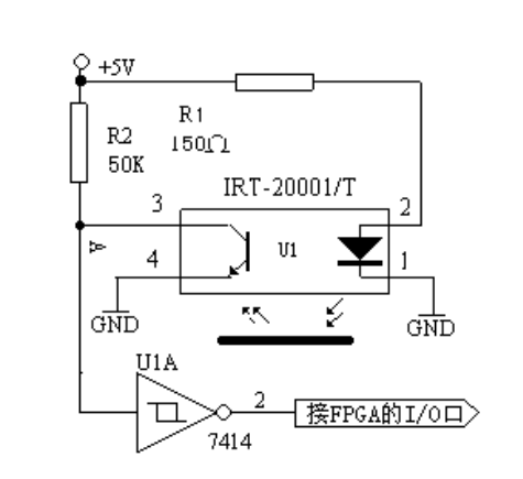
Photoelectric Detection Circuit
06.
Display Circuits
LED (Light Emitting Diode) displays are the most commonly used display devices made up of light-emitting diodes. Digital LED displays use seven light-emitting diodes to display numbers, commonly referred to as seven-segment LED displays or digital tubes. Additionally, there is a dot-type light-emitting diode in the digital tube used to display the decimal point.
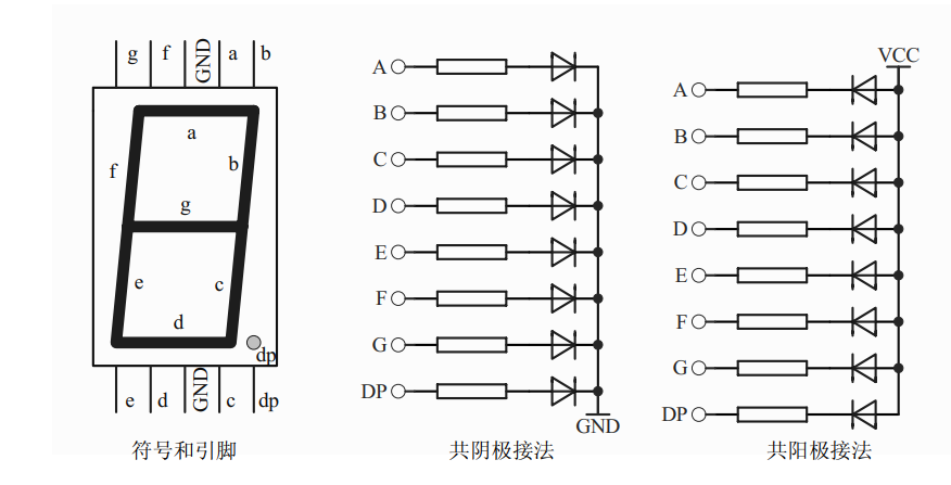
Internal Structure of LED Display
The principle of LCD display is that under the action of an external electric field, the liquid crystal rod-shaped molecules with dipole moments in the liquid crystal display device change their arrangement state, modulating the light passing through the liquid crystal display device, thus presenting a display effect of light and dark or transparent and opaque. Below is the method and program for driving a dot matrix character LCD module (MDLS) with FPGA.
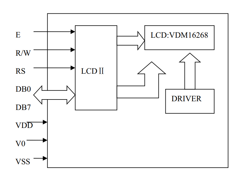
Block Diagram of LCD Display Module Circuit

Screenshots of Electronic Books in the Complete Hardware Learning Material Collection

[Complete Set of Hardware Learning Material Collection]