“Is multi-axis linkage always ‘fighting’? Is the circular arc trajectory drawn as ‘jagged’? The Mitsubishi RD78G’s PLC OPEN instructions make complex motion control as simple as building with Legos!”
No need to delve into the underlying code, 3-step axis group construction + 2 interpolation secrets, hands-on guidance to achieve 16-axis coordination, precise linear positioning, and smooth circular drawing.
📌 Highlights of this issue:
1.🔧16-axis linkage zero-error configuration: Multi-axis synchronization system optimization strategy
2.📏Four-axis synchronouslinear interpolation: High-precision trajectory planning technology
3.🔄 Circular interpolation stability assurance: Key parameter optimization guide for CircMode
01
Part
【Axis Group Construction: The ‘Foundation Project’ of Multi-Axis Coordination】
Why must we build the axis group first? Want the robotic arm to draw circles or the 3D printer to move in a straight line? A single axis is a “lone ranger”, while an axis group is a “symphony orchestra”!
The RD78G supports 16-axis grouping, but a single misconfiguration = total collapse!
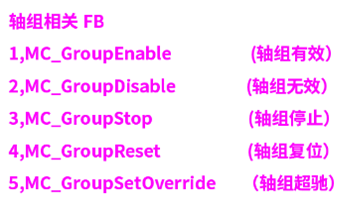
Figure 1
Axis group monitoring data
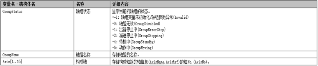
Figure 2
✅ Four steps to configure the axis group:
Create a single axis
Navigation window → [Axis] → right-click → [New Data] → set axis name
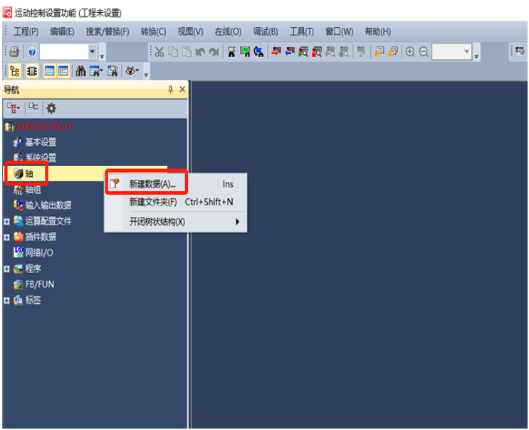
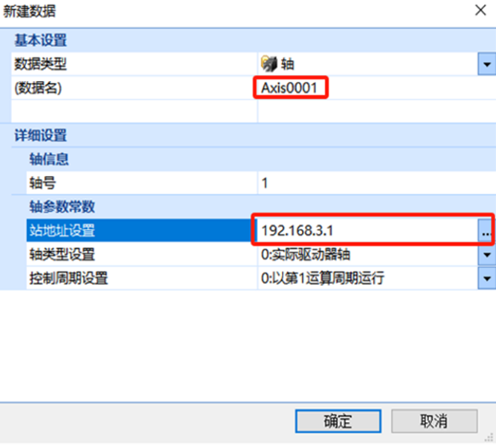
Figure 3
Create an axis group
Navigation window → [Axis Group] → right-click → [New Data] → create AXES_GROUP type variable
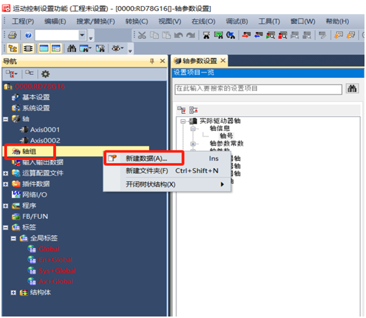
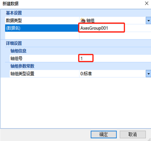
Figure 4
Add constituent axes
Enter [Axis Group Settings] → [Configure Axis] → input required axis names → [Apply]
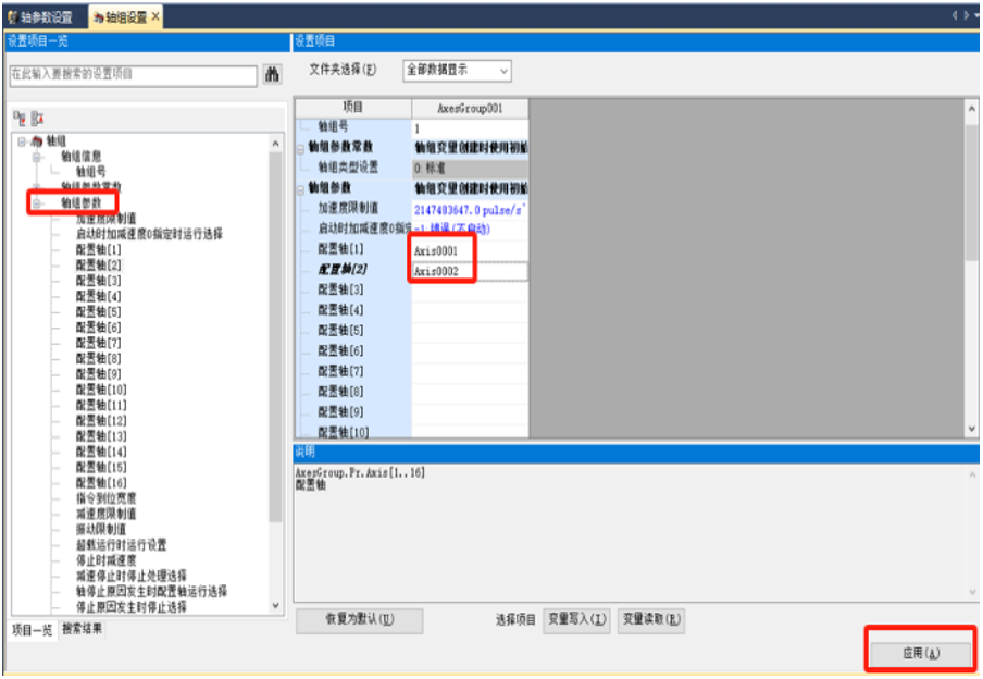
Figure 5
📊 Real-time monitoring can be obtained through GroupStatus to get the current axis group operating status, facilitating debugging and fault diagnosis.
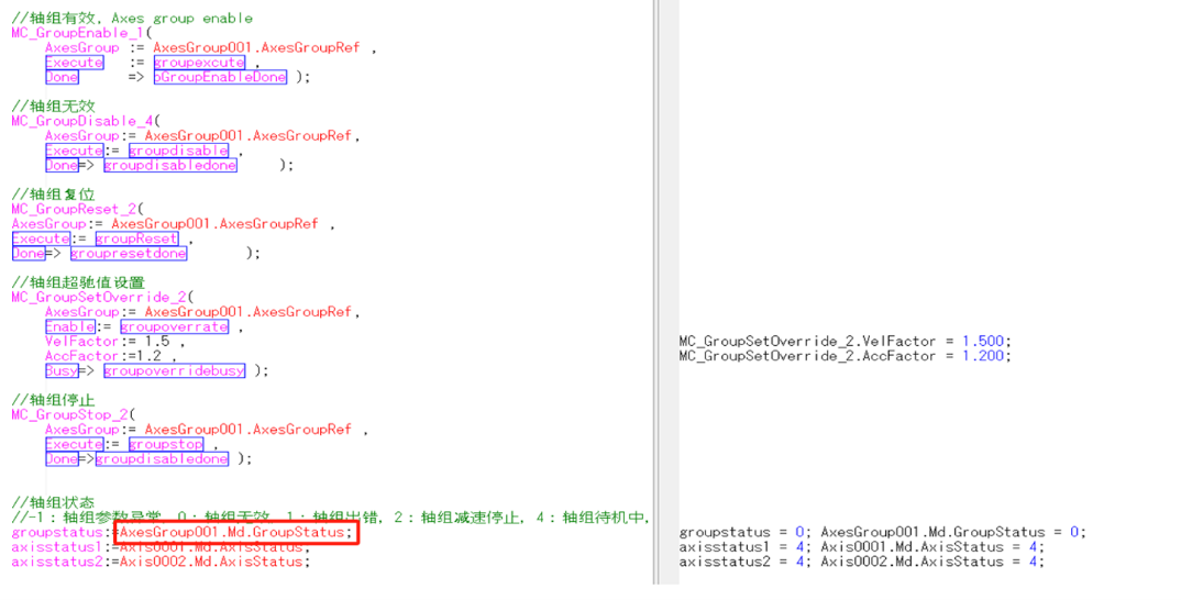
Figure 6
02
Part
【Linear Interpolation: The ‘Steady as a Rock’ Secret for Four-Axis Synchronous Straight Movement】
✅ Scene Pain Point: Is the handling robotic arm always shaking during diagonal movement?
RD78G Solution: MCv_MoveLinearInterpolate instruction, choose between relative/absolute coordinates!

Figure 7
Programming Key Points:
Create a local label array (16 elements) in the program block to pass the movement amounts of each axis
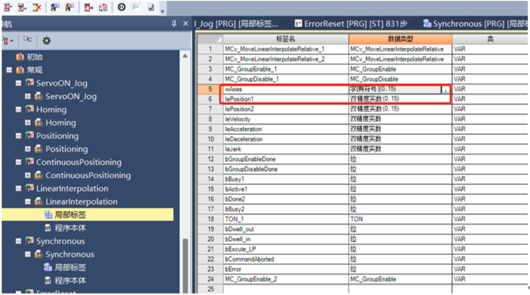
Figure 8
Online monitoring can be used to view the position, speed, and other states during the interpolation process.
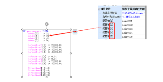
Figure 9
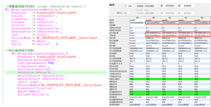
Figure 10
03
Part
【Circular Interpolation: The Ultimate Guide to Avoiding ‘Trajectory Collapse’】
Core Logic: Center Mode (CircMode=1) is the safest,
Boundary Point Mode (=0) is bound to fail!
🔧 3 steps to complete the basic configuration of RD78G
The prerequisite for circular interpolation iscorrectly configuring the motion control system.
Just 3 steps to quickly build the basic environment:
1. Add motion module
-
Navigation window → “Parameters” → “Module Information” → right-click → [Add New Module] → select RD78G8
2. Set network and servo parameters
-
Enter “Module Parameters (Network)” → configure servo IP address and basic parameters → click [Apply] to save
3. Create axis group (Key)
-
“Module Extension Parameters” → “Axis” → add servo axes → enable soft limits
-
Create “Axis Group” → add the axes involved in interpolation to the group (e.g., 2 axes for X-Y plane linkage)
📐Circular interpolation FB function block: Parameter details + practical logic
RD78G achieves circular control through MCv_MoveCircularInterpolateAbsolute (absolute) and MCv_MoveCircularInterpolateRelative (relative) two major function blocks.Parameter settings are the key to success!
✅ Core parameter quick reference table (with pitfall guide)
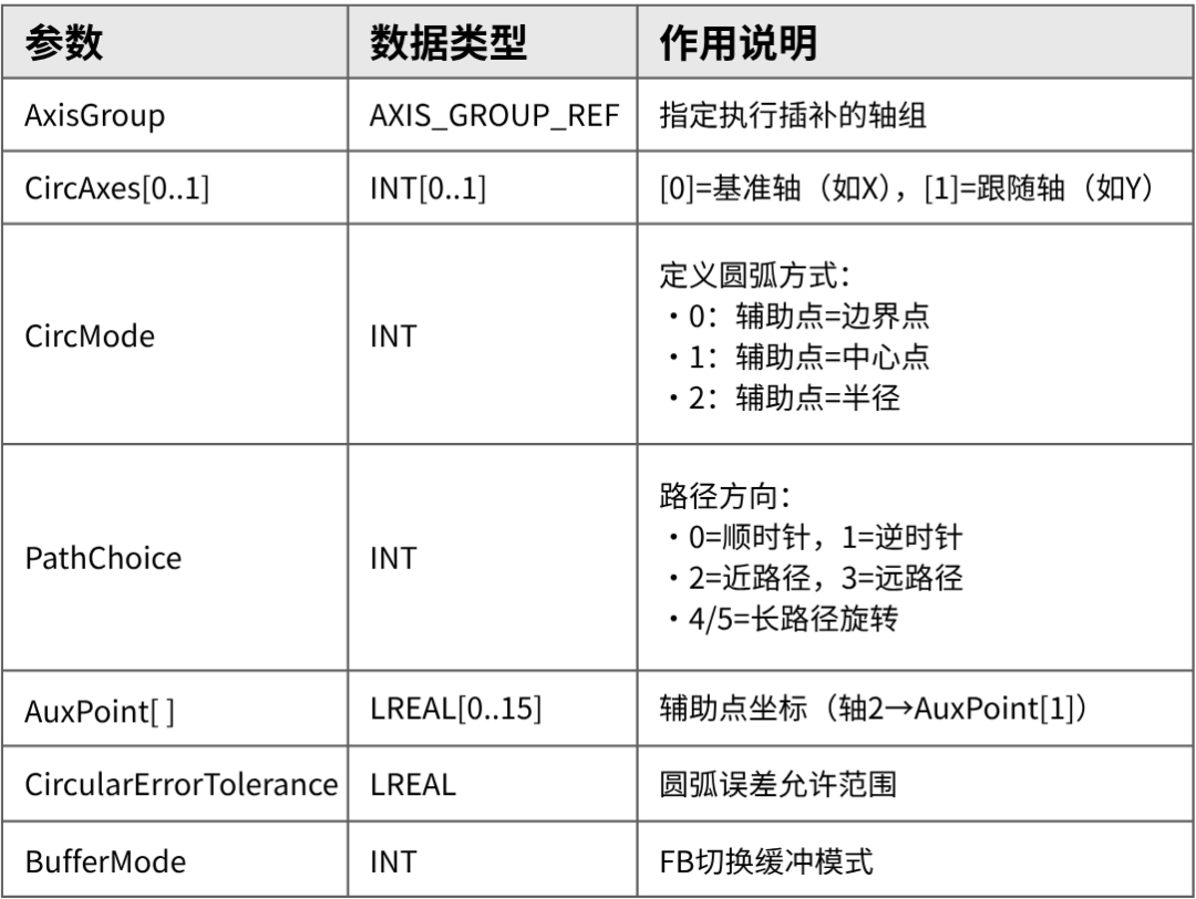
Table 1
🌟 In-depth analysis of key parameters
1. Incorrect CircMode = trajectory collapse!
-
Using center point mode (CircMode=1) is the safest: Fill in the center coordinates in AuxPoint, fill in the endpoint coordinates in EndPoint, and select PathChoice 0 (clockwise) or 1 (counterclockwise) to accurately draw the arc.
-
Avoid using boundary point mode (CircMode=0): prone to trajectory deviation due to calculation errors!
2. PathChoice anti-short-arc technique
When the angle from start point to endpoint < 180°:
-
Go short arc clockwise → PathChoice=0
-
Go long arc counterclockwise → PathChoice=3 (example: when processing a semicircle, select PathChoice=3 to prevent trajectory “shrinking”)
💻 Program Example
MC_GroupEnable (axis group valid)
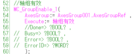
Figure 11
MCv_MoveCircularInterpolateAbsolute (absolute circular interpolation control)
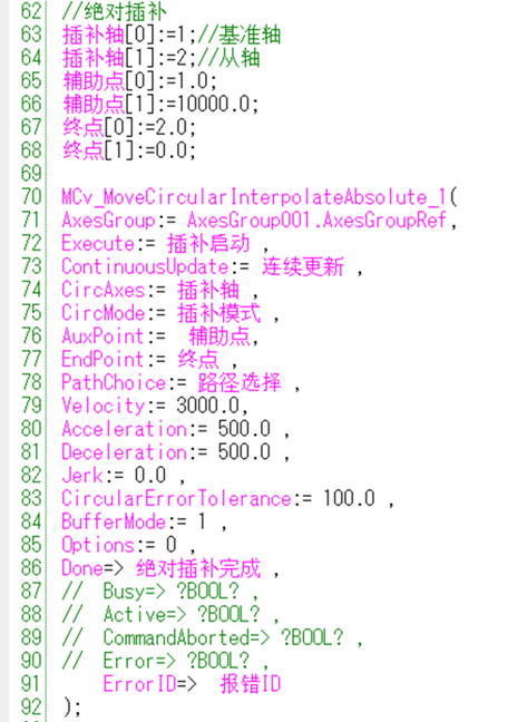
Figure 12
MCv_MoveCircularInterpolateRelative (relative circular interpolation control)
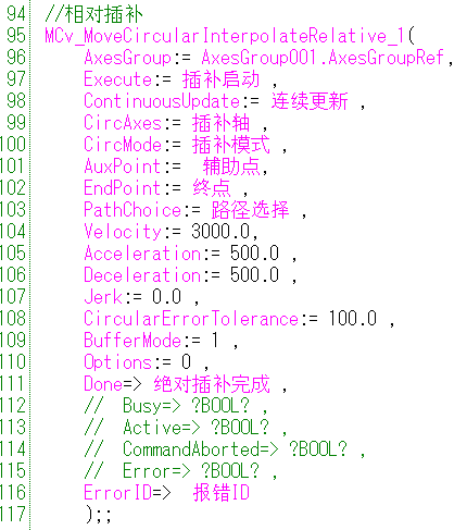
Figure 13
💬 Interactive Session:
👉 Have you ever been caught in a circular interpolation pitfall? Share your story in the comments:
More practical technical videos
Click the icon below to enter
[bilibili]
Learn it!

Accumulating helps growth, learning creates value! In the future, we will continue to explain Mitsubishi Electric’s FA system-related products. If you have any doubts during practical operations, or if there are any products or functions you need to understand, feel free to leave comments and suggestions! Please continue to follow the “Mitsubishi Machine Applications” technical short videos! All video copyrights belong to Mitsubishi Electric Automation, and unauthorized use is prohibited.
For more information, please follow us

Mitsubishi Electric Automation China brand