Design of the Fiber Optic Network for the Reflector Control System of China’s FAST Telescope
CAA
Wisdom sets sail, creating the future together
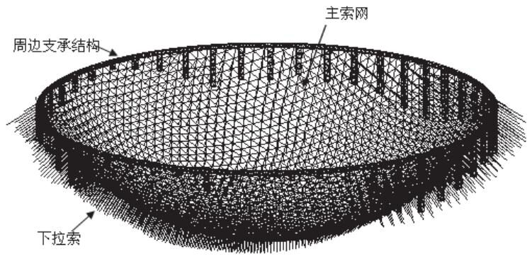
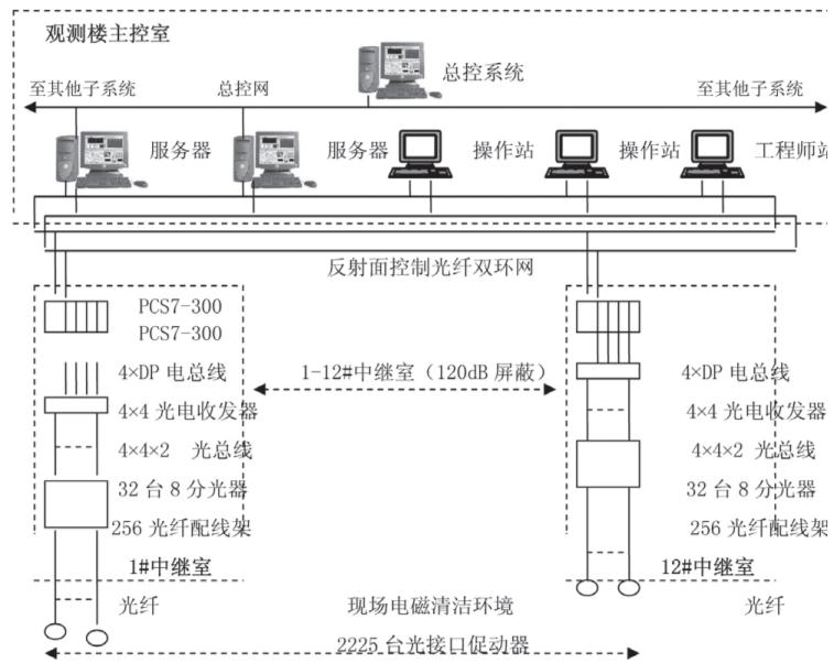
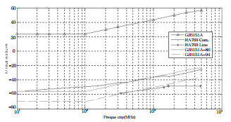
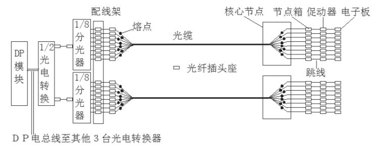
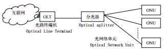
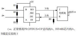
1OverviewThe Five-hundred-meter Aperture Spherical radio Telescope (FAST) is the world’s largest single-aperture radio telescope. As a multidisciplinary basic research platform, FAST has the capability to extend neutral hydrogen observations to the edge of the universe, observe dark matter and dark energy, and explore the origin and evolution of the universe; it can discover thousands of pulsars in one year and study the structure and physical laws of matter under extreme conditions; it hopes to discover strange stars and quark stars; discover neutron star-black hole binaries without relying on models to accurately determine black hole mass; detect gravitational waves by accurately measuring the arrival time of pulsars; join the international very long baseline network for ultra-fine structure imaging of celestial bodies; and may also discover high-redshift giant pulsar galaxies, achieving the first observation breakthrough of methanol pulsars outside the Milky Way; used to search for and identify possible interstellar communication signals, looking for extraterrestrial civilizations, etc.FAST can also extend China’s space measurement and control capabilities from geostationary orbit to the outer edges of the solar system, increasing deep space communication data downlink rates by 100 times. The timing measurement precision of pulsars has been improved from the current 120 nanoseconds to 30 nanoseconds, making it the most precise pulsar timing array internationally and creating pulsar clocks for autonomous navigation research. It conducts high-resolution microwave surveys, diagnosing and identifying weak space signals at a resolution of 1Hz, serving national security as a passive strategic radar. As an incoherent scattering radar receiving system of the “Meridian Project”, it provides high resolution and high efficiency for ground observations; tracks and detects coronal mass ejection events, serving space weather forecasting, etc. Its effects are shown in Figure 1.Figure 1: Effect Diagram of FAST2BASIC STRUCTURE OF FASTOne of the main basic structures of FAST is the construction of a 500-meter diameter ring beam using natural karst topography, relying on the ring beam to weave a spherical cable net with 6725 steel cables, as shown in Figure 2. Triangular aluminum panels with an edge length of about 12 meters are fully laid on 4600 mesh holes to reflect electromagnetic waves. 2225 cable net nodes are pulled down by hydraulic actuators “actuators” with a certain tension, stretching the cable net into a reference spherical surface. During astronomical observations, some nodes are further tightened while others are relaxed according to calculations to form a parabolic surface with a diameter of 300 meters and a focal ratio of 0.47, with the focal point located at the feed (receiving device) suspended in the sky by steel cables, to focus the received cosmic radio signals. The control system synchronizes the focus of the reflector and the feed device to move over time to track or actively observe a celestial body. On a large scale, the cable net steel cables are equivalent to springs, deforming under the pull of the actuator, forming a parabolic surface whose focus direction can be controlled and moved, thus achieving the focusing of weak cosmic electromagnetic signals. The working frequency band of FAST is 70MHz~3GHz (wavelength 0.1~4.3 meters).Figure 2: Schematic Diagram of the Cable Net Structure3FAST CONTROL SYSTEMAccording to the requirements of FAST for reflector control, an industrially mature PLC controller is used to build the control system as shown in Figure 3. The FAST master control system compiles and issues observation commands to various subsystems based on the requirements of astronomers, and the reflector control system parses this observation command and translates it into position control instructions for the 2225 node actuators.Figure 3: Block Diagram of the FAST Reflector Control SystemIn terms of control content, the reflector control is not a high-speed control system (node scanning cycle of 0.5 seconds, node position accuracy RMS 20mm). However, it has two characteristics that are usually absent in industrial control systems. First, the large number of nodes requires high reliability, and the actuator nodes are distributed in a topography that is not very regular (there are no regular wiring bridge channels based on industrial devices), and more severely, there are extremely stringent electromagnetic compatibility requirements. Because FAST is used to receive extremely weak cosmic radio signals, the International Telecommunication Union (ITU) has electromagnetic radiation requirements for the radio astronomy background that are 10,000 times stricter than national military standards (80dB) and above. The blue line above in Figure 4 is the GJB151A standard for military equipment electromagnetic sensitivity requirements, the red solid line below is the limit after subtracting 80dB, the red dashed line is the limit after subtracting 94dB, and the blue line below is the recommended continuous and spectral line observation limit value RA769 by the ITU. There are basically no such strict requirements in conventional industrial control systems. At the same time, Guizhou is a region with frequent lightning strikes, and large-scale lightning protection in the wild must be a key consideration. Surge protectors (SPD) can limit induced lightning voltage to below 1.5kV, and if combined with EMI filters, they will have better suppression of instantaneous overvoltage, typically limiting it to a few hundred volts.Figure 4: Comparison of GJB151A Standards and ITU-R RA769 Limit RequirementsTo meet the requirements of electromagnetic shielding, all power entering the shielding space must pass through a “through-wall” power filter, whose ingress and egress lines are mutually invisible to prevent electromagnetic interference from passing through line-to-line inductive coupling. The signal optical fibers enter and exit the shielding space through waveguide tubes. Electromagnetic sealing is different from water and gas medium sealing; theoretically, the thickness of electromagnetic waves is about 0. If there are non-conductive continuous long narrow seams at the connection points of the shielding conductor, although the seams are so narrow that they may not leak water or gas, electromagnetic waves can still pass smoothly, and the wavelength that passes is proportional to the longest continuous length of the seam. For deep holes, electromagnetic waves below the cutoff frequency will produce significant attenuation when passing through. Therefore, electromagnetic waves that can easily pass through deep holes for water and gas mediums are difficult to pass through. Note that when the optical cable passes through the waveguide tube, any possible metallic reinforcement must be removed, as the metal wire may act as an antenna, emitting indoor electromagnetic signals from the shielding room to the outside, thus destroying the shielding function, as shown in Figure 5.Figure 5: Schematic Diagram of Optical Fiber and Power Passing Through Shielding Space InterfaceSimple Design Method for Circular Waveguide Tube:Cutoff frequency: fc=17.6/D (GHz), where D is the inner diameter of the waveguide tube, in cm.FAST operates in the frequency band of 70MHz~3GHz, and fc should be selected >3GHz. For example, if fc=15GHz, then approximately:Insertion loss: A=32L/D (dB), where L is the length of the waveguide tube, in cm.Based on these characteristics, the reflector control system takes the following measures:(1) Disperse the risk of PLC controllers by building 12 relay rooms with a shielding effectiveness of 120db distributed in the depression. Each relay room installs a Siemens PCS7-300 controller and 4 Profibus-DP field bus interface cards. Each DP bus logically connects about 50 node actuators, collectively responsible for controlling about 200 actuators nearby. A total of 12×4=48 DP buses connect all 2225 actuators. To solve the difficulties of signal filtering and cable shielding and to avoid lightning strike risks, the Profibus-DP field bus uses optical fiber transmission. These 12 sets of PCS7-300 controllers are connected via a single-mode optical fiber dual-ring network Profinet and the observation building communication server. Any single point failure in the main ring network immediately changes the information flow direction to ensure normal communication through the self-healing function. However, if two points fail simultaneously or a switch fails, the system automatically switches communication from the main ring to the backup ring, ensuring normal communication as well. The distance from the reflector site to the main observation building is 1000 meters, while the distance between relay rooms is about a few hundred meters, and the distance from the relay room to the nearest actuator is in the range of 50~300 meters. This is not a long distance for single-mode optical fiber.(2) The actuators use smart hydraulic actuators with optical interfaces, which not only perform functions but also have local closed-loop, diagnostic, protection, and health management functions. Therefore, they can only achieve multi-information bidirectional transmission through Profibus-DP field bus digital communication and the system.The system and 2225 actuators require 2225 bus optical interfaces. If conventional optoelectronic conversion modes are used, it will result in a large number of devices, occupying a large cabinet volume, generating significant heat, and increasing complexity, which will lead to reduced system reliability. The Profibus-DP communication protocol is a single master-slave protocol, and the system communicates with the actuators in a broadcast manner. At any time, at most only one actuator can respond to the main system, and there are no communication requirements between the actuators that serve as slaves. Based on these technical characteristics, we adopted the already mature passive optical network technology (PON) used in Internet technology to greatly simplify the optical network structure, reduce the number of devices and the corresponding device occupancy space and power consumption heat.Due to the development of Ethernet and optical fiber technology and the pursuit of performance and cost issues for optical network access, the price of Ethernet switch optical fiber interfaces is difficult for households to bear, which led to the proposal of Ethernet passive optical network (EPON) technology in the 1990s. After 20 years of development, it has now matured and been widely used. A typical PON system configuration is shown in Figure 6.Figure 6: Passive Optical Network (PON) System DiagramOne of the key components in the PON system is the optical splitter. It is a passive pure optical component, manufactured using either fused taper or planar waveguide methods. It does not require power, does not generate heat, and is inexpensive. The main optical path is distributed to each branch optical path, and conversely, each branch return light has the functionality of “vector summation” in the main optical path. The technical characteristics of data transmission in PON basically meet the requirements of the Profibus-DP communication protocol, but there are also two characteristics:· The light emitted by the OLT is divided into multiple parts, and the energy of each beam will be attenuated proportionally. Each division results in approximately -3dB of light loss (i.e., 10log0.5). This loss needs to be compensated by the light-emitting power or receiving sensitivity.· Any ONU that is not in a communication state cannot be in a light logic 1 state (i.e., having light).We choose the technical specifications of optical-electrical transceiver modules produced domestically:Rate 0~2Mbps; Emission intensity ≥ -5dBm; Sensitivity better than -25dBm; Emission wavelength 1550nm; Reception wavelength 1310nm.The formula for optical path energy balance is as follows:Light emission power – all losses – backup margin ≥ receiving sensitivityGenerally consider optical fiber joint loss of 0.15~0.2dB; optical fiber fusion loss of 0.1dB; optical fiber distance loss is wavelength-dependent, roughly selected as 0.25~0.4dB/km; backup energy margin is usually considered as 5~8dB. An example calculation is as follows:-5dBm (emission power) = -25dBm (receiving sensitivity) + 2dB (various joint losses) + 11dB (1:8 splitter loss) + 5dB (backup margin) + L×0.4dB/km (optical fiber distance loss)We can calculate the distance that can be reliably transmittedL = (25-5-2-11-5)/0.4 = 2/0.4 = 5km > 0.3kmInterestingly, one should not simply think that reversing the input and output of the splitter creates what is called a “light synthesizer”. Even if the light from two branches from the same light source is synthesized through a splitter, a stable intensity doubling synthesized light cannot be obtained. This is because monochromatic laser has frequency phase vector summation factors, resulting in peaks that, while doubled, exhibit irregular full-amplitude unstable light signals.Passive optical networks can only be used in serial communication types without network conflicts, such as Modbus and Profibus-DP, which comply with this regulation. However, communication protocols with network conflicts, such as CAN, cannot be used.By using a 1:8 splitter, the system saves 7/8 = 87.5% of traditional optoelectronic converters, significantly reducing power consumption heat, space occupancy, and cost. At the same time, the number of electrical nodes in the Profibus-DP network is also reduced proportionally, which can reduce or eliminate the need for repeaters, thus this scheme has significant advantages. The question is, wouldn’t using a 1:16 splitter yield even better results? Indeed, it would, but the limiting factor is that the current low-frequency optoelectronic transceiver module products’ receiving sensitivity is not sufficient to compensate for the higher splitting loss. The receiving sensitivity of optoelectronic transceiver modules for Ethernet signals without DC components can reach -35dB, thus allowing the use of 1:64 splitters. Figure 7 shows an example of the optical path connection from the relay room PLC cabinet to the actuator’s electronic board.Figure 7: Optical Path Connection Diagram from 1/4 DP Bus to Actuator’s 16-way Optical PathRS485 transceivers have two usages: one is to use under CPU control as a communication port for “smart” devices, where all transceiving states are under planned control by the CPU. The second is to use as a repeater, in which case it is completely unaware of the signal’s direction and baud rate. There are two types of methods to solve direction and baud rate recognition control. One method is to use CPU or FPGA-type chips, which are generally considered more complex and difficult to adapt to high-speed communication. The second is a hardware-based method, which is simpler but requires the communication protocol’s link layer to adhere to certain rules, namely that the first bit of each “byte” forming the information frame must start with a negative transition from 1 to 0, and all nodes in idle state listen, with the bus remaining in logical “1”. For example, mainstream communication protocols such as Modbus and Profibus-DP comply with this regulation. This allows us to design the RS485 transceiver as follows:Idle State: Listening state/RE=DE=0, bus state is 1, RO output is 1;Receiving State: Listening state/RE=DE=0, bus receives information, RO outputs according to received information;Sending State: When DI=0/RE=DE=1, the sending state, bus state is 0, RO is high impedance, pulled up by an external resistor to logical 1, consistent with idle state. This is a true sending process.When DI=1/RE=DE=0, the chip is nominally in the sending state but is actually receiving. The bus is high impedance, just like the idle state, also pulled up to logical 1 by an external resistor, only just “looks like” it sent a 1.Therefore, we can consider that the so-called sending process actually only sent a logical 0, while logical 1 is the result of the bus bias naturally formed. The repeater does no extra work on the data, thus achieving protocol independence, baud rate self-adaptation, and transparent data transmission. The pull-up resistor on RO is to ensure that during such a “sending” process, RO maintains logical 1 without change. The receiving state/RE=DE=0 is conventional use, with nothing special.The Profibus-DP communication physical layer adopts RS485 specifications, with the master station remaining in logical “1” state during idle time, which does not affect the reception from the slave station. However, it is not compliant with PON requirements for slave actuators to also remain in logical “1” state during idle time. Therefore, it is necessary to reverse the signal sent from the slave station, so that in idle state it is in logical “0”, meaning no light. After the master station’s optoelectronic transceiver receives it, it is reversed again to restore it to meet the original communication requirements. A very simple way to reverse the signal at the master station is to reverse the bus terminals A and B of the 485 chip, while changing the original pull-up resistor RO to ground, i.e., pull-down. This way, sending and receiving are reversed simultaneously, and similar changes are also needed on the slave actuator side to maintain consistency on both sides. The configuration diagram of the master station RS485 transceiver is shown in Figure 8, noting that the 4 bias matching resistors R1 extbackslash2 extbackslash3 extbackslashRO are essential.Figure 8: Master Station Protocol Independent, Baud Rate Self-Adaptive,Signal Reversing RS485 Transceiver★ Funded by the National Natural Science Foundation Project “Control Strategy and Adaptive Modeling Research for the FAST Active Reflector Network” (Project No: 11273001)Author IntroductionZhu Lichun (1964-), female, from Chifeng, Inner Mongolia, researcher, PhD, doctoral supervisor, chief engineer of the control system of the 500-meter aperture spherical radio telescope FAST at the National Astronomical Observatory, graduated from the Department of Telecommunications Engineering of Beijing University of Posts and Telecommunications in 1986, and obtained a PhD from the Graduate School of the Chinese Academy of Sciences, majoring in radio astronomy technology and methods, mainly engaged in research on measurement and control technology methods.Zhang Weijie (1963-), from Beijing, senior engineer, project manager at Taiji Computer Co., Ltd., graduated from Beijing University of Technology in 1987, mainly engaged in design, construction, installation, management, and on-site debugging in related industries such as industrial automation.Si Ke Ke (1945-), male, from Dongyang, Zhejiang, professor-level senior engineer, deputy chief engineer (retired) of the Metallurgical Automation Research and Design Institute, graduated from Tsinghua University in 1970 from the Department of Radio, engaged in research, product development, and engineering contracting of industrial automation measurement and control technology methods and equipment.