
Background of the CAN Protocol
In the 1980s, the number of electronic control units (ECUs) in automobiles gradually increased, and traditional point-to-point electrical communication methods were becoming inadequate. The point-to-point connections between each electronic control unit and other devices made system wiring complex, costly, and prone to failures. Automakers sought a communication method that could simplify wiring while meeting the real-time control and high reliability requirements of vehicles.
Development History of the CAN Protocol
Bosch realized that electronic devices in vehicles (such as engine management, body control, etc.) needed a more reliable and efficient communication network. Therefore, Bosch began developing a communication system specifically designed for vehicles.
-
1986: Release of the CAN Protocol:
Bosch officially released the preliminary specifications of the CAN protocol in 1986 and showcased it at the **SAE International Congress and Exposition** held that same year.
-
1987: First CAN Controller:
Bosch collaborated with Infineon (then Siemens Semiconductor Division) to launch the world’s first CAN controller chip, marking the practical application of the CAN protocol in the automotive electronics market.
-
1991: ISO Standardization:
The CAN protocol passed the review by the International Organization for Standardization (ISO) in 1991 and became the ISO 11898 standard. This standard specified the physical layer and data link layer of the CAN protocol, further promoting its application in the industry.
-
1990s: Widespread Application:
With the development of automotive electronics technology, the CAN protocol rapidly gained popularity and became the standard communication protocol for most automakers. The application of CAN networks in automobiles expanded from engine control units (ECUs) to anti-lock braking systems (ABS), body control modules (BCM), on-board diagnostic systems (OBD), and more.
Based on CAN, Bosch also developed CAN FD (Flexible Data-rate CAN), aimed at increasing data transmission speed and frame capacity to meet the higher bandwidth requirements in automobiles. The CAN FD protocol was officially released in 2012 and has been promoted in automotive and other high-demand industrial applications.
Impact of the CAN Protocol
The introduction of the CAN protocol fundamentally changed the architecture of automotive electronic systems, greatly simplifying communication between electronic devices in vehicles, making automotive systems more efficient, reliable, and scalable. Its low cost, high real-time performance, and high reliability characteristics have led to the widespread application of CAN not only in the automotive industry but also in industrial automation, medical equipment, rail transportation, and other fields.
Main Features of CAN Communication
1. Multi-Master Structure:
CAN adopts a multi-master architecture, meaning multiple nodes can send messages simultaneously, avoiding bottlenecks from a single master device.
2. No Central Controller:
All nodes can autonomously send and receive messages without a master-slave distinction, reducing dependence on a central node.
3. Message Priority and Arbitration Mechanism:
Each CAN message frame has a unique identifier (ID). When multiple nodes send data simultaneously, the message with the higher priority identifier gains access to the bus without causing conflicts.
4. Fast Error Detection and Recovery:
CAN has mechanisms such as CRC checking, error frame detection, and automatic retransmission, which can detect errors in real-time and automatically recover communication, ensuring high reliability of data transmission.
5. Short Data Frame Structure:
A single CAN data frame can contain a maximum of 8 bytes of data; although the frame structure is small, it ensures high real-time performance and low latency.
The transmission rate of CAN communication ranges from 10 kbps to 1 Mbps, depending on the application scenario and bus length.
2. Frame Format of CAN Data Frame
Frame Format of Standard CAN Data Frame
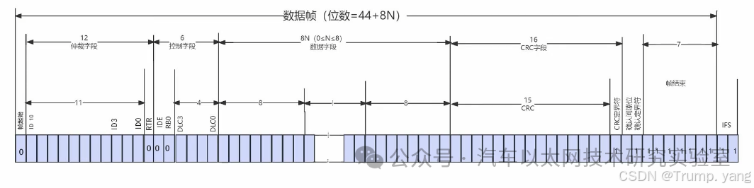
The frame format of the standard CAN data frame (CAN 2.0A, 11-bit identifier) consists of the following parts, each serving a different purpose, with specific fields as follows:
-
-
Indicates the beginning of the data frame, which is a dominant bit (logical low), marking the end of the bus idle state and the start of data transmission.
2. Identifier (Identifier) (also referred to as Arbitration Field in some materials):
-
-
Used to indicate the priority and source of the data frame. The priority of the identifier is determined by its numerical value; the smaller the value, the higher the priority. During bus arbitration, the identifier’s priority determines which node can send data.
3. Remote Transmission Request (RTR):
Indicates the frame type:
Data Frame: This bit is a dominant bit (0).
Remote Frame: This bit is a recessive bit (1), indicating a request for a node to send data.
IDE (Identifier Extension Bit): 1 bit, distinguishes between standard frames (11-bit ID) and extended frames (29-bit ID). For standard frames, IDE is a dominant bit (0).
Reserved Bit: 2 bits, reserved for future use, default to dominant bit (0).
Data Length Code (DLC): 4 bits, indicates the number of bytes in the data segment, ranging from 0 to 8 bytes.
Contains the actual data being transmitted, with the length determined by the DLC field, allowing a maximum of 8 bytes. Each data frame of the CAN standard frame can transmit up to 8 bytes of data.
6. Cyclic Redundancy Check (CRC):
15-bit CRC field and 1 bit CRC delimiter.
Used to detect errors during data transmission. The sender calculates the CRC checksum based on the data frame, and the receiver performs the same calculation and comparison to ensure data integrity.
7. Acknowledgement Field (ACK):
1 bit ACK slot: The sender sets this bit to a recessive bit (1), and the receiver sets it to a dominant bit (0) after successfully receiving and verifying the frame, indicating successful reception.
1 bit ACK delimiter: Fixed as a recessive bit (1), used to mark the end of the ACK slot.
Indicates the end of the data frame, all recessive bits (logical high).
Structure Diagram of Standard CAN Data Frame
-
Arbitration Mechanism:Each node on the CAN bus performs arbitration by sending identifiers; the smaller the identifier, the higher the priority.
-
High Reliability::Ensured by CRC checks and ACK response mechanisms for correct data transmission and reception.
-
Real-time Performance:Achieved through short frame designs (up to 8 bytes of data) and arbitration mechanisms for fast data transmission, especially suitable for low-latency scenarios in automotive and industrial applications.
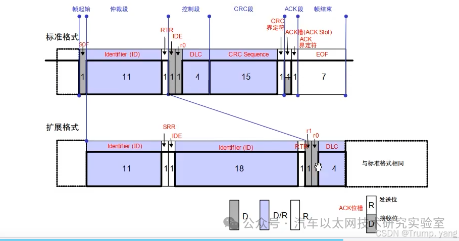
Frame Format of CAN Extended Frame
The main difference between the extended data frame (CAN 2.0B) and the standard data frame (CAN 2.0A) lies in the length of the identifier and the corresponding changes in the control field. The extended data frame allows for longer identifiers for more complex application scenarios.
Identifier length is 11 bits.
The range of identifiers that can be represented by an 11-bit identifier is from 0x000 to 0x7FF (0 to 2047), totaling 2048 different identifiers.
Identifier length is 29 bits, consisting of an 11-bit base identifier and an 18-bit extended identifier.
The range of identifiers that can be represented by a 29-bit identifier is from 0x00000000 to 0x1FFFFFFF (0 to 536870911), totaling 536870912 different identifiers.
IDE Bit (Identifier Extension Bit)
IDE bit is a dominant bit (0), indicating this is a standard frame.
IDE bit is a recessive bit (1), indicating this is an extended frame.
Contains only one 11-bit identifier.
Contains one 11-bit base identifier plus an 18-bit extended identifier, totaling a 29-bit identifier.
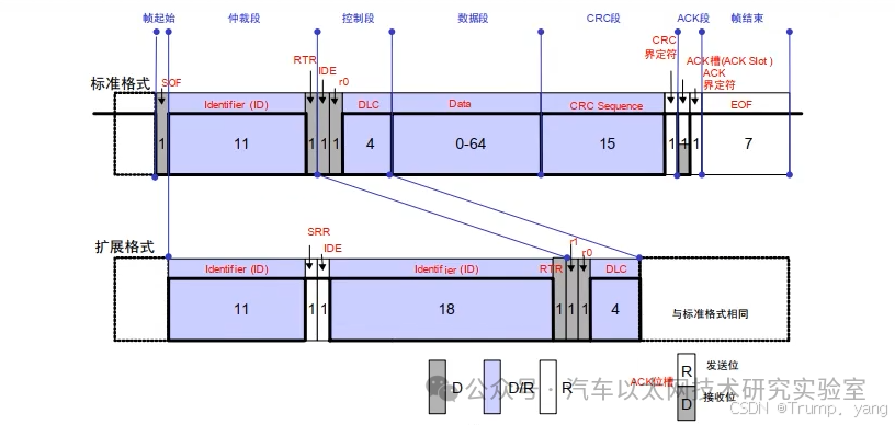
During the arbitration process, the standard data frame has a higher priority than the extended data frame because in the comparison of the IDE bit, the dominant bit (0) takes precedence over the recessive bit (1).
Frame Format of CAN Remote Frame
The remote frame (Remote Frame) is a type of frame in the CAN communication protocol used to request other nodes to send data frames with a specified identifier. Unlike data frames, remote frames do not carry data; they only contain the identifier of the data type the sender wishes to receive. When a node sends a remote frame, nodes with the same identifier will respond by sending the corresponding data frame.
Functions of Remote Frame:
-
Request Data:A node requests other nodes to send data frames with a specific identifier by sending a remote frame.
-
Communication Control:Used to control data transmission of specific identifiers without occupying too much bandwidth.
Differences Between Remote Frame and Data Frame:
-
Data Frame:Contains a data field and transmits the actual data to the receiving node.
-
Remote Frame:Does not have a data field and is only used to request specific identifiers’ data.
Frame Format of Remote Frame:
The frame structure of the remote frame is basically the same as that of the standard data frame and the extended data frame, with the only difference being that the RTR (Remote Transmission Request) bit of the remote frame is set as a recessive bit (1), indicating that this is a remote frame rather than a data frame.
Frame Format of CAN Error Frame
The error frame is a special frame in the CAN bus used to identify and notify nodes on the bus of transmission errors. Unlike regular data frames or remote frames, error frames do not carry data; instead, they signal other nodes on the bus that an error has occurred.
Differences Between Error Frame and Regular Data Frame
-
Data Frame:Used to transmit actual data between nodes.
-
Error Frame:Used to notify all nodes on the bus of a transmission error, requiring the current transmission to be discarded and triggering a retransmission.
2. Different Frame Structures:
Error frames have a completely different structure from data frames, consisting of two main parts:
-
Active Error Flag or Passive Error Flag:
-
Error Frame Consists of Two Parts:
-
Divided into Active Error Flag and Passive Error Flag.
-
Active Error Flag: The sender sends six consecutive dominant bits (logical 0). Any node in an active error state can send this flag to notify that an error has occurred.
-
Passive Error Flag: The sender sends six consecutive recessive bits (logical 1). When a node enters a passive error state, it sends this flag instead of dominant bits.
-
Eight recessive bits (logical 1).
-
Used to mark the end of the error frame and ensure a clear boundary between the error frame and subsequent data frames.
When a node detects an error and is in an active state, it sends an active error frame:
-
Active Error Flag: Composed of six **dominant bits (0)**, used to notify the bus that an error has occurred.
-
Error Delimiter: Eight recessive bits (1), used to mark the end of the error frame.
Active Error Frame Format:

When a node enters a passive error state, it sends a passive error frame:
-
Passive Error Flag: Composed of six **recessive bits (1)**, indicating that the node has entered a passive error state.
-
Error Delimiter: Eight recessive bits (1), the same as in the active error frame.
Passive Error Frame Format:

Trigger Conditions for Error Frame:
-
Bit Error:The node detects that the bus state does not match expectations when sending a dominant bit (or recessive bit).
-
Stuff Error:The CAN bus specifies that after five consecutive identical bits, an opposite bit should be inserted as a stuffing bit. If the stuffing bit is incorrect, it triggers an error.
-
CRC Error:The CRC checksum calculated by the receiver does not match the CRC checksum in the data frame.
-
Form Error:The structure or delimiter of the frame does not comply with the specifications of the CAN protocol.
-
ACK Error:The sender did not detect an acknowledgment signal from the receiver (the ACK bit was not pulled low by the receiver).
3. Bit Stuffing in CAN Data Transmission
Bit Stuffing is a technique in the CAN (Controller Area Network) protocol used to ensure synchronization on the bus and avoid long periods of continuous identical levels, helping the receiver correctly recover the clock and bit timing.
-
In CAN communication, whenever the sender detects five consecutive identical bits (whether dominant or recessive) in the data stream, it automatically inserts an opposite bit.
-
This additional inserted bit is called a stuffing bit.
-
Bit stuffing applies to all bit streams included in the control field, data field, CRC field, etc., but does not apply to fixed-length fields (e.g., the frame’s ACK, SOF, EOF, etc.).
Suppose during data transmission, the sender sends a continuous bit stream of 11111, a stuffing bit of 0 will be automatically inserted on the CAN bus, and the transmitted data will become 111110. If sending 00000, a 1 will be inserted, changing it to 000001.
Functions of Bit Stuffing
1. Maintaining Bus Synchronization:
-
CAN bus uses non-return to zero (NRZ) encoding, which is prone to producing sequences of consecutive identical levels, making it difficult for the receiver to detect bit boundaries and affecting clock synchronization.
-
Through bit stuffing, periodic level changes can be generated on the CAN bus, helping receiving nodes correctly synchronize their clocks.
2. Preventing Long Periods of Constant Level:
-
If the level on the CAN bus remains unchanged for a long time, the receiving node’s clock may become unsynchronized, leading to incorrect data parsing.
-
Bit stuffing forces the insertion of opposite levels on the bus, ensuring changes in the bit stream and enhancing signal reliability.
-
The receiver also checks for stuffing bits according to the same rules; if the received data does not have stuffing bits inserted as per the rules or if the stuffing bits are incorrect, the receiver can determine that the data frame has an error, triggering an error frame.
-
Bit stuffing errors are one of the common types of CAN errors, referred to as stuffing errors.
Working Mechanism of Bit Stuffing
-
The sender automatically detects each segment of five consecutive identical bits while sending frames.
-
If five identical bits are found, an opposite bit is inserted afterward.
-
The receiver checks stuffing bits according to the same rules upon receiving data.
-
Once an error is detected (e.g., consecutive identical bits not having opposite bits inserted), it is deemed a stuffing error.
Suppose the sender wants to send a binary data stream of 01111110; we can observe the bit stuffing process through the following steps:

-
Scan the bit stream from left to right, finding five consecutive 1s.
-
According to the bit stuffing rule, an opposite bit 0 must be inserted after 11111.

Thus, through bit stuffing, the sequence of consecutive identical bits is broken, ensuring that the receiver can maintain synchronization.
Bit stuffing applies to most parts of the CAN frame, including:
-
Data Field (actual data bits)
-
-
Control Field (e.g., Identifier)
Parts Where Bit Stuffing Is Not Applicable:
-
SOF (Start of Frame): The frame’s start flag does not undergo bit stuffing.
-
ACK (Acknowledgment Field): Used to confirm receipt of the data frame, also does not undergo stuffing.
-
EOF (End of Frame): The frame’s end flag also does not undergo bit stuffing.


Source: Trump. Yang
*Disclaimer: This article is either original or forwarded by the author. If it unintentionally infringes on someone’s intellectual property, please inform us for deletion. The above images and text are sourced from the internet; if there is any infringement, please contact us in a timely manner, and we will delete it within 24 hours. The content of the article reflects the author’s personal views, and the Automotive Ethernet Technology Research Laboratory reprints it only to convey a different perspective, which does not represent the laboratory’s endorsement or support of this viewpoint. If there are any objections, please contact the Automotive Ethernet Technology Research Laboratory.
https://blog.csdn.net/weixin_46999174/article/details/142312539