
Welcome FPGA engineers to join the official WeChat technical group
ClickBlue TextFollow us at FPGA Home – the best and largest pure FPGA engineer community in China
Communication issues, like traffic problems, can also have various situations such as high speed, low speed, congestion, interruption, etc. If we compare serial communication to traffic, UART can be likened to a station, and a frame of data is like a car. Cars on the road must follow traffic rules. If it’s in the city, the speed limit is generally 30 or 40, while on highways it can be up to 120. The path a car takes and the speed limit depend on the protocol specifications. Common serial port protocols include RS-232, RS-422, and RS-485. What are the subtle differences between them? Let’s explore together.
1. What is UART
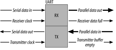
UART stands for Universal Asynchronous Receiver/Transmitter, commonly referred to as UART, which is a key module for asynchronous communication between devices. UART is responsible for handling the serial/parallel and parallel/serial conversion between the data bus and the serial port, and it defines the frame format. As long as both communicating parties adopt the same frame format and baud rate, they can complete the communication process using just two signal lines (Rx and Tx) without sharing a clock signal, thus it is also called asynchronous serial communication.
By adding a suitable level converter, such as SP3232E or SP3485, UART can also be used for RS-232 and RS-485 communication or connected to a computer port. UART has a wide range of applications, including in mobile phones, industrial control, PCs, etc.
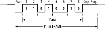
UART uses asynchronous serial communication. Serial communication refers to transmitting data one bit at a time over a single transmission line. The characteristics include simple communication lines, low-cost implementation using simple cables, and suitability for long-distance communication, but with slower transmission speeds. Asynchronous communication uses one character as the transmission unit, and the time interval between two characters in communication is not fixed, while the time interval between two adjacent bits within the same character is fixed. The data transmission rate is expressed in baud rate, which is the number of binary bits transmitted per second. For example, if the data transmission rate is 120 characters/second, and each character consists of 10 bits (1 start bit, 7 data bits, 1 parity bit, 1 stop bit), the baud rate would be 10×120=1200 characters/second=1200 baud. The data communication format is shown in the figure below: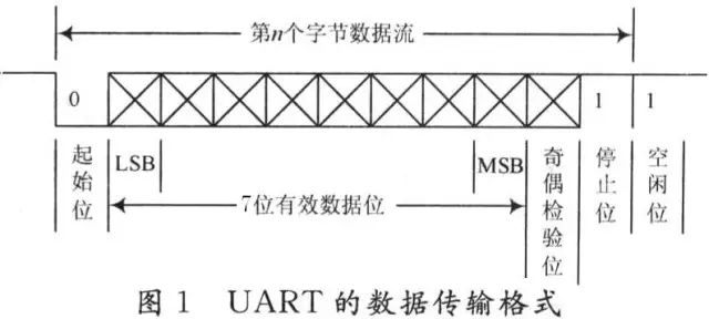 The meanings of each bit are as follows: Start bit: A logical “0” signal is sent first, indicating the start of the transmission character. Data bits: Can be 5 to 8 bits of logical “0” or “1”. For example, ASCII code (7 bits), extended BCD code (8 bits). Little-endian transmission. Parity bit: Adding this bit to the data bits ensures that the number of “1” bits is even (even parity) or odd (odd parity). Stop bit: It is a character data end flag, which can be 1 bit, 1.5 bits, or 2 bits of high level. Idle bit: Remains in a logical “1” state, indicating no data transmission on the current line. Note: Asynchronous communication is character-based; the receiving device can correctly receive data as long as it maintains synchronization with the sending device within the transmission time of one character after receiving the start signal. The arrival of the next character’s start bit recalibrates the synchronization (achieved by detecting the start bit for self-synchronization of the clocks of the sender and receiver).
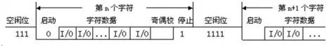
2. RS-232 Standard
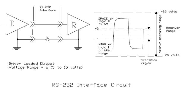
RS-232 is a serial physical interface standard established by the Electronic Industry Association (EIA) in the United States. RS is an abbreviation for “Recommended Standard”, and 232 is the identification number. RS-232 specifies electrical and physical characteristics and only applies to the data transmission path; it does not include data processing methods. It should be noted that many people often mistakenly refer to RS-232, RS-422, and RS-485 as communication protocols, which is incorrect. They are merely mechanical and electrical interface standards related to UART communication (at most, they pertain to the physical layer of network protocols).
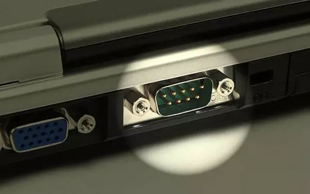
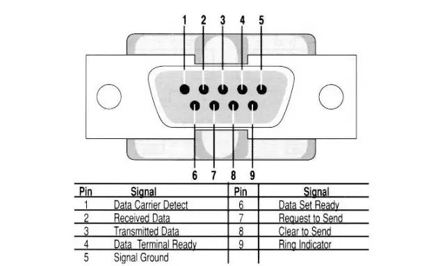
The standard specifies the use of a 25-pin DB-25 connector, defining the signal content for each pin of the connector, as well as the voltage levels for various signals. Later, IBM simplified RS-232 to a DB-9 connector for PC machines, which has become the de facto standard today. In industrial control, the RS-232 port generally only uses three lines: RXD (2), TXD (3), and GND (5).
 In the early days, since PCs all had RS-232 interfaces, we chose RS-232 when we needed to use UART. However, personal computers, including laptops and desktops, no longer come with RS-232 interfaces, and people see that there is no DB9 connector on the motherboard. Therefore, development boards now typically opt for TTL UART or directly implement UART to USB on the development boards.
In embedded systems, the serial port generally refers to the UART port, but we often confuse it with the COM port and the relationships between RS232, TTL, etc. In fact, UART and COM refer to the physical interface form (hardware), while TTL and RS-232 refer to the voltage standards (electrical signals).
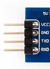
UART has 4 pins (VCC, GND, RX, TX), using TTL levels, where low level is 0 (0V) and high level is 1 (3.3V or above).
3. RS-485/RS-422 Standards
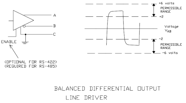
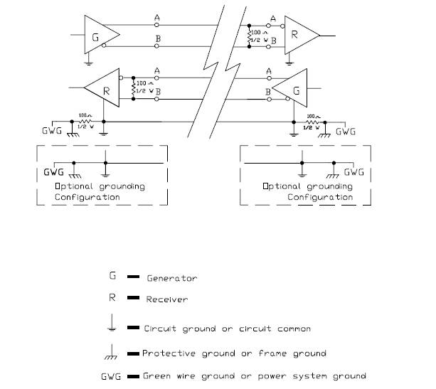
The RS-232 interface can achieve point-to-point communication, but this method cannot realize networking functionality. Therefore, to solve this problem, a new standard, RS-485, was developed. RS-485 uses differential transmission for data signals, also known as balanced transmission, employing a pair of twisted wires, defining one wire as A and the other as B.
Typically, the positive voltage between the sending driver A and B is +2 to +6V, representing one logic state, while the negative voltage is -2 to 6V, representing another logic state. There is also a signal ground C, and RS-485 includes an “enable” terminal, which is optional in RS-422.
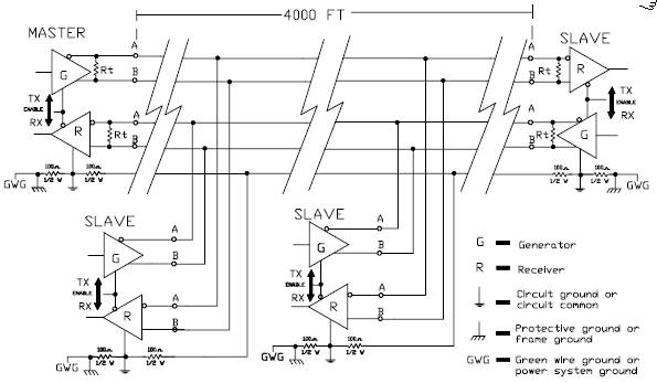
RS-422 has the same electrical performance as RS-485. The main difference is that RS-422 has 4 signal lines: two for sending and two for receiving. Because RS-422 separates receiving and sending, it can receive and send simultaneously (full duplex). This full duplex requirement necessitates separate channels for sending and receiving, making RS-422 suitable for communication between two stations, star networks, and ring networks, but not for bus networks; RS-485 only has 2 signal lines, so it can only operate in half-duplex mode, commonly used in bus networks.
1. The electrical characteristics of RS-485: Logic “1” is represented by the voltage difference of +(2~6)V between the two wires; Logic “0” is represented by the voltage difference of -(2~6)V between the two wires. The interface signal levels are lower than those of RS-232-C, making it less likely to damage the interface circuit chips, and this level is compatible with TTL levels, facilitating connection with TTL circuits.
2. The maximum data transmission rate of RS-485 is 10Mbps.
3. The RS-485 interface employs a combination of balanced drivers and differential receivers, enhancing the ability to withstand common-mode interference, thus providing good noise immunity.
4. The maximum communication distance for RS-485 is approximately 1219M, with a maximum transmission rate of 10Mb/S. The transmission rate is inversely proportional to the transmission distance; at a transmission rate of 100Kb/S, the maximum communication distance can be achieved. If longer distances are needed, RS-485 repeaters should be added. The RS-485 bus generally supports a maximum of 32 nodes; if special 485 chips are used, it can reach 128 or 256 nodes, with a maximum of 400 nodes.
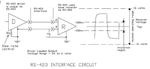
1 RS-423 Unbalanced Serial Communication Interface
Structure, Signal Levels, Transmission Distance, Transmission Rate, Interface Chips
2 RS-422 Balanced Serial Communication Interface
Structure, Signal Levels, Interface Chips, MC3486, MC3487, SN75154, SN75155
Transmission Rate, Transmission Distance
3 RS-485 Serial Communication Bus
Structure, Signal Levels, Interface Chips MAX485
Transmission Rate, Transmission Distance, Application Examples
Due to the early emergence of the RS-232 interface standard, it inevitably has shortcomings, mainly the following four points:
(1) The signal level values of the interface are relatively high, making it easy to damage interface circuit chips. Additionally, since the 232 levels are not compatible with TTL levels, level conversion circuits are required to connect with TTL circuits;
(2) The transmission rate is relatively low; in asynchronous transmission, the baud rate is 20Kbps. Now, due to the use of new UART chips, baud rates have reached 115.2Kbps (1.832M/16);
(3) The interface uses one signal line and one signal return line to form a common-ground transmission form, which is prone to common-mode interference, resulting in weak noise immunity;
(4) The transmission distance is limited, with a maximum standard transmission distance of 50 meters, and in practice, it can only be used at around 15 meters;
(5) RS-232 only allows one-to-one communication without considering the formation of a serial bus. (This point is very important; in many control scenarios, one master device needs to communicate with multiple slave devices point-to-point, resulting in a spiderweb wiring layout on-site.)
Unbalanced Serial Communication Interfaces RS-423, RS-449
Balanced Serial Communication Interface RS-422
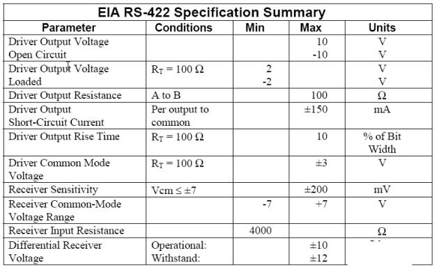
RS-422 (EIA RS-422-A Standard) is the serial port connection standard for Apple’s Macintosh computers. RS-422 uses differential signals, while RS-232 uses unbalanced reference ground signals. Differential transmission employs two wires to send and receive signals; compared to RS-232, it offers better noise immunity and greater transmission distances. In industrial environments, better noise immunity and longer transmission distances are significant advantages.
4. Comparison Between RS-232 and RS-485
1. Noise Immunity: The RS-485 interface uses a combination of balanced drivers and differential receivers, providing good noise immunity. The RS-232 interface uses one signal line and one signal return line to form a common-ground transmission, which is prone to common-mode interference.
2. Transmission Distance: The maximum transmission distance for the RS-485 interface is 1200 meters (at 9600bps), and it can actually reach 3000 meters. The RS-232 transmission distance is limited, with a maximum standard transmission distance of 50 meters, and practically it can only be used at around 15 meters.
3. Communication Capability: The RS-485 interface allows for up to 128 transceivers on the bus, enabling users to easily establish a device network using a single RS-485 interface. RS-232 only allows one-to-one communication.
4. Transmission Rate: RS-232 has a lower transmission rate, with a baud rate of 20Kbps in asynchronous transmission. The RS-485 maximum data transmission rate is 10Mbps.
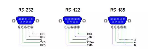
5. Signal Lines: The RS-485 interface forms a half-duplex network, typically requiring only two signal lines. The RS-232 port generally uses RXD, TXD, and GND, totaling three lines.
6. Electrical Level Values: The logic “1” for RS-485 is represented by a voltage difference of + (2-6)V between the two wires; for logic “0”, it is represented by a voltage difference of – (2-6)V between the two wires. In RS-232-C, the voltage of any signal line is in a negative logical relationship. That is, logic “1” is -5 to -15V; logic “0” is +5 to +15V.
5. Comparison Between RS-422 and RS-485
The electrical performance of RS-485 is identical to that of RS-422. The main differences are:
1. RS-422 has 4 signal lines: two for sending (Y, Z) and two for receiving (A, B). Since RS-422 separates receiving and sending, it can receive and send simultaneously (full duplex).
2. RS-485 has only two data lines: sending and receiving are both A and B. Since RS-485 shares the two lines for receiving and sending, it cannot receive and send simultaneously (half duplex).
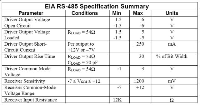
The RS-485 standard employs balanced transmission and differential reception to drive the bus, with specific specifications required:
The receiver’s input resistance RIN ≥ 12kΩ
The driver must output a common-mode voltage of ±7V
The input capacitance ≤ 50pF
In the case of 32 nodes with 120Ω termination resistance, the driver must still output at least 1.5V (the size of the termination resistance is related to the parameters of the twisted pair used).
The receiver’s input sensitivity is 200mV (i.e., (V+) – (V-) ≥ 0.2V indicates signal “0”; (V+) – (V-) ≤ -0.2V indicates signal “1”).
Due to the long-distance, multi-node (32 nodes), and low cost of transmission lines, the EIA RS-485 standard has become the preferred standard for data transmission in industrial applications.
(1) The electrical characteristics of RS-485: The transmitter: Logic “0” is represented by a voltage difference of + (2~6)V between the two wires; logic “1” is represented by a voltage difference of – (2~6)V between the two wires. The receiver: If A is higher than B by more than 200mV, it is considered logic “0”; if A is lower than B by more than 200mV, it is considered logic “1”;
(2) The maximum data transmission rate of RS-485 is 10Mbps. However, since RS-485 often needs to communicate with the RS-232 port of a PC, the practical maximum is usually 115.2Kbps. A higher transmission rate can reduce the transmission distance of RS-485, so it is often around or below 9600bps;
(3) The RS-485 interface employs a combination of balanced drivers and differential receivers, providing good noise immunity;
(4) The maximum transmission distance standard for RS-485 is 1200 meters (at 9600bps), but it can actually reach 3000 meters. The RS-485 interface allows for up to 128 transceivers on the bus, meaning RS-485 has multi-machine communication capabilities, allowing users to easily establish a network using a single RS-485 interface. Since the RS-485 interface forms a half-duplex network, it typically only requires two signal lines, so RS-485 interfaces are generally implemented using twisted pair cables. The international standard for RS-485 does not specify connector standards for RS-485 interfaces, so terminal blocks or DB-9, DB-25, etc., can all be used.
When using the RS-485 interface, the maximum allowed cable length for data signal transmission from generator to load depends on the specific cable diameter and is a function of the data signal rate. This length is primarily limited by signal distortion and noise. The relationship between maximum cable length and signal rate is obtained using 24AWG copper twisted telephone cable (diameter of 0.51mm), with an inter-wire bypass capacitance of 52.5PF/M and a terminal load resistance of 100 ohms (as referenced in GB11014-89 Appendix A). When the data signal rate is reduced to below 90Kbit/S, assuming the maximum allowed signal loss is 6dBV, the cable length is limited to 1200m. In practice, it is entirely possible to achieve longer cable lengths. When using cables of different diameters, the maximum cable length will vary. For example, when the data signal rate is 600Kbit/S, using 24AWG cable, the maximum cable length is 200m; if using 19AWG cable (diameter of 0.91mm), the cable length can exceed 200m; if using 28AWG cable (diameter of 0.32mm), the cable length can only be less than 200m.
For long-distance communication with RS-485, it is recommended to use shielded cables and ground the shielding layer.
6. Three Factors Affecting RS-485 Bus Communication Speed and Reliability
1. Signal Reflection in Communication Cables
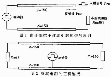
During communication, two signal factors can cause signal reflection: impedance discontinuity and impedance mismatch.
Impedance discontinuity occurs when the signal suddenly encounters a cable impedance that is very low or non-existent at the end of the transmission line, causing reflection at that point, similar to how light reflects when it enters a different medium. To eliminate this reflection, a termination resistor that matches the characteristic impedance of the cable must be bridged at the end of the cable to ensure impedance continuity. Since signals are transmitted bidirectionally on the cable, a matching termination resistor can also be bridged at the other end of the communication cable.
From a theoretical analysis, as long as a termination resistor that matches the characteristic impedance of the transmission cable is bridged at the end of the transmission cable, no reflection phenomenon should occur. However, in practical applications, due to the characteristic impedance of the transmission cable being related to the communication baud rate and other environmental factors, the characteristic impedance cannot be perfectly equal to the termination resistor, so some degree of signal reflection will still exist.
Another cause of signal reflection is the mismatch of impedance between the data transceiver and the transmission cable. This type of reflection mainly manifests when the communication line is idle, causing data confusion in the entire network.
The impact of signal reflection on data transmission ultimately arises because the reflected signal triggers the comparator at the receiver’s input, causing the receiver to receive incorrect signals, leading to CRC check errors or errors in the entire data frame.
In signal analysis, the parameter used to measure the strength of the reflected signal is the Reflection Attenuation Factor (RAF). Its calculation formula is as follows (1).
RAF=20lg(Vref/Vinc) (1)
Where: Vref—Voltage magnitude of the reflected signal; Vinc—Voltage magnitude of the incident signal at the connection point of the cable and transceiver or termination resistor.
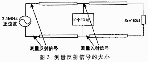
The specific measurement method is illustrated in the figure. For example, if the peak-to-peak value of the incident signal sine wave at 2.5MHz is +5V, and the peak-to-peak value of the reflected signal is +0.297V, then the reflection attenuation factor of this communication cable at a communication rate of 2.5MHz is:
RAF=20lg(0.297/2.5)=-24.52dB
To mitigate the impact of reflected signals on communication lines, noise suppression and bias resistor methods are usually employed. In practical applications, for relatively small reflected signals, the bias resistor method is often used for simplicity and convenience. The principle of how to improve communication reliability through bias resistors in communication lines.
2. Signal Attenuation in Communication Cables
The second factor affecting signal transmission is the attenuation of the signal during transmission through the cable. A transmission cable can be viewed as an equivalent circuit formed by distributed capacitance, distributed inductance, and resistance, as shown in the figure.
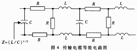
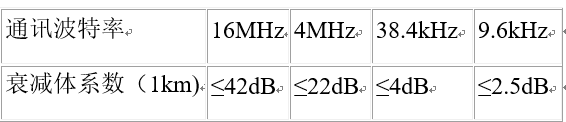
The distributed capacitance C of the cable is mainly produced by the two parallel conductors of the twisted pair. The resistance of the conductors has a negligible effect on the signal and can be ignored. The signal loss is primarily due to the LC low-pass filter formed by the distributed capacitance and distributed inductance of the cable. The attenuation coefficients of the standard LAN-type two-core cables used in PROFIBUS (the standard cable selected by Siemens for the DP bus) at different baud rates are shown in Table 1.
The cable attenuation coefficients
3. Pure Resistive Load in Communication Cables
The third factor affecting communication performance is the size of the pure resistive load (also known as DC load). The pure resistive load here mainly consists of termination resistors, bias resistors, and RS-485 transceivers.
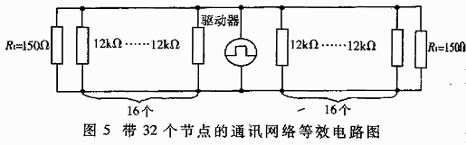
When discussing the EIA RS-485 specification, it was mentioned that the RS-485 driver can output at least 1.5V of differential voltage when connected to 32 nodes with a 150Ω termination resistor. The input resistance of one receiver is 12kΩ, and the entire network’s equivalent circuit is shown in Figure 5. Based on this calculation, the load capacity of the RS-485 driver is:
RL=32 input resistors in parallel with 2 termination resistors=((12000/32)×(150/2))/(12000/32)+(150/2))≈51.7Ω
Currently, commonly used RS-485 drivers include MAX485, DS3695, MAX1488/1489, and SN75176A/D used by Holley, among others. Some RS-485 drivers can achieve load capacities of up to 20Ω. Without considering many other factors, based on the relationship between driving capacity and load, a driver can support a maximum number of nodes far exceeding 32.
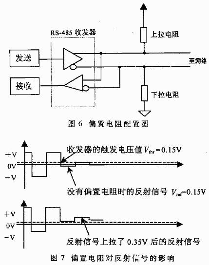
When the communication baud rate is relatively high, bias resistors are very necessary. The connection method for bias resistors is shown in Figure 6. Their role is to pull the level on the bus away from 0V when there is no data (idle state) on the bus, as shown in Figure 7. This way, even if small reflected signals or interference occur in the line, the data receivers connected to the bus will not malfunction due to these signals.
Through the following example, the size of the bias resistor can be calculated:
Termination resistors Rt1=Rr2=120Ω;
Assuming the maximum peak-to-peak value of the reflected signal Vref≤0.3Vp-p, then the negative half-cycle voltage Vref≤0.15V; the reflected current Iref due to the termination resistor is ≤0.15/(120||120)=2.5mA. The hysteresis voltage value of general RS-485 transceivers (including SN75176) is 50mV, that is:
(Ibias-Iref)×(Rt1||Rt2)≥50mV
Thus, it can be calculated that the bias current Ibias≥3.33mA
+5V=Ibias(R上拉+R下拉+(Rt1||Rt2)) (2)
Using Equation (2), it can be calculated that R上拉=R下拉=720Ω
In practical applications, there are two methods for adding bias resistors to the RS-485 bus:
(1) Distributing the bias resistors evenly to each transceiver on the bus. This method adds a bias resistor to each transceiver connected to the RS-485 bus, providing each transceiver with a bias voltage.
(2) Using a pair of bias resistors on a section of the bus. This method is effective for large reflected signals or interference signals present on the bus. It is important to note that the addition of bias resistors increases the load on the bus.
7. The Relationship Between RS-485 Bus Load Capacity and Communication Cable Length
When designing the network configuration (bus length and number of loads) for the RS-485 bus, three parameters should be considered: pure resistive load, signal attenuation, and noise margin. The pure resistive load and signal attenuation have been discussed earlier; now we will discuss noise margin. The noise margin for RS-485 bus receivers should be at least greater than 200mV. The previous discussion assumed a noise margin of 0. In practical applications, to enhance the bus’s anti-interference capability, it is always desired that the noise margin of the system exceeds the requirements stipulated in the EIA RS-485 standard. The relationship between the number of loads on the bus and the communication cable length can be seen from the following formula:
Vend=0.8(Vdriver-Vloss-Vnoise-Vbias)(3)
Where: Vend is the signal voltage at the end of the bus, which is defined as 0.2V during standard measurement; Vdriver is the output voltage of the driver (related to the number of loads. For 5 to 35 loads, Vdriver=2.4V; when the number of loads is less than 5, Vdriver=2.5V; when the number of loads exceeds 35, Vdriver≤2.3V); Vloss is the loss of the signal during transmission in the bus (related to the specifications and length of the communication cable), calculated using the standard cable’s attenuation coefficient provided in Table 1, where the attenuation coefficient b=20lg(Vout/Vin); Vnoise is the noise margin, defined as 0.1V during standard measurement; Vbias is the bias voltage provided by the bias resistors (typical value is 0.4V).
In Equation (3), the multiplication by 0.8 is to prevent the communication cable from entering a fully loaded state. From Equation (3), it can be seen that the size of Vdriver is inversely related to the number of loads on the bus, and the size of Vloss is inversely related to the length of the bus; the other parameters depend only on the type of driver used. Therefore, once the driver for the RS-485 bus is selected, the maximum distance that the signal can be transmitted is directly related to the number of loads on the bus at a fixed communication baud rate. The specific relationship is: within the allowable range of the bus, the more loads it carries, the shorter the signal transmission distance; the fewer loads it carries, the farther the signal transmission distance can be.
8. The Impact of Distributed Capacitance on RS-485 Bus Transmission Performance
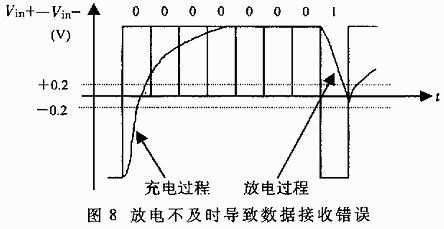
The distributed capacitance of the cable is mainly generated by the two parallel conductors of the twisted pair. Additionally, there is distributed capacitance between the conductors and ground, which, although small, should not be ignored in analysis. The impact of distributed capacitance on bus transmission performance primarily arises because the transmitted signal on the bus is a fundamental wave signal, with signal representation only as “1” and “0”. In special bytes, such as 0x01, the signal “0” allows sufficient charging time for the distributed capacitance, while when the signal “1” arrives, due to the charge in the distributed capacitance, it fails to discharge in time, resulting in (Vin+) – (Vin-) still being greater than 200mV, leading the receiver to mistakenly identify it as “0”, ultimately causing CRC check errors and errors in the entire data frame transmission. The specific process is illustrated in the figure.
Due to the distributed effects on the bus, data transmission errors occur, resulting in a decrease in overall network performance. Two methods can solve this problem:
(1) Reducing the data transmission baud rate;
(2) Using cables with lower distributed capacitance to improve the quality of transmission lines.
Simply connecting the A and B ends of each interface with a pair of twisted wires without grounding the signal of the RS-485 communication link can work in some cases, but it poses risks to the system. The RS-485 interface transmits signals using a differential method without needing a reference point to detect the signal system; it only needs to detect the potential difference between the two wires. However, it should be noted that the transceiver can only function normally when the common-mode voltage does not exceed a certain range (-7V to +12V). When the common-mode voltage exceeds this range, it can affect communication reliability or even damage the interface. As shown in Figure 1, when transmitter A sends data to receiver B, the common-mode voltage at transmitter A’s output is VOS. Due to the existence of ground potential differences VGPD between the two systems, the common-mode voltage at the receiver’s input can reach VCM=VOS+VGPD. The RS-485 standard specifies VOS≤3V, but VGPD can vary significantly (dozens of volts) and may be accompanied by strong interference signals, causing the receiver’s common-mode input VCM to exceed the normal range, generating interference currents on the signal line that affect normal communication or damage the equipment.
Conclusion:
The serial port is a very versatile device interface, commonly used as a communication interface for instruments and equipment, often employed for remote data collection or remote control. The development of serial ports is relatively straightforward, making them one of the favorite interfaces for many engineers.

Welcome communication engineers and FPGA engineers to follow our public account

The largest FPGA WeChat technical group in the country

We welcome everyone to join the national FPGA WeChat technical group, which has tens of thousands of engineers, a group of technology-loving engineers, where FPGA engineers help each other and share knowledge in a strong technical atmosphere! Hurry up and invite your friends to join!!

Press and hold to join the national technical group for FPGA

FPGA Home Component Market

Advantageous component services, please scan to contact the group owner: Jin Juan Email: [email protected] Welcome recommendations for procurement

ACTEL, AD part of the advantageous orders (operating the full series):

XILINX, ALTERA advantageous stock or orders (operating the full series):

(Above components are partial models, for more models please consult group owner Jin Juan)

Service concept: FPGA Home Component Market aims to facilitate engineers to quickly and conveniently purchase components. After years of dedicated service, our customer service is spread across large listed companies, military research units, and small and medium enterprises. Our biggest advantage is the service-first concept, and we achieve fast delivery and favorable prices!

Directly operated brands: Xilinx ALTERA ADI TI NXP ST E2V, Micron, and more than a hundred component brands, especially proficient in components subject to embargoes from Europe and the United States. We welcome engineering friends to recommend us to procurement or consult us directly! We will continue to provide the best service in the industry!

Official thanks to brands in the FPGA technical group: Xilinx, intel (Altera), microsemi (Actel), Lattice, Vantis, Quicklogic, Lucent, etc.