In automotive Passive Entry Passive Start (PEPS) systems using low power Bluetooth® technology, drivers enter and start the engine using a key card that communicates with the car’s access system (instead of a traditional key).
Figure 1 shows a typical architecture of low power Bluetooth PEPS inside the vehicle. This architecture includes a central smart key module and nine satellite modules. The nine satellite modules shown here are for illustration; the actual number of satellite modules may vary in practical applications. Figure 1 also illustrates how these modules communicate using a communication bus.
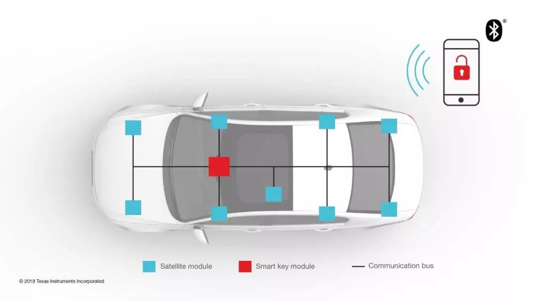
Figure 1: Low Power Bluetooth PEPS Architecture Inside the Vehicle
Inside the Satellite Node
So what is inside the satellite node? Figure 2 shows a typical block diagram of a low power Bluetooth satellite module. This module includes a low power Bluetooth System on Chip (SoC) (such as TI’s SimpleLink™ CC2640R2F-Q1), a power supply, and a communication interface (usually a transceiver). Figure 2 also shows other modules within the PEPS system, including the smart key module and even the body control module.
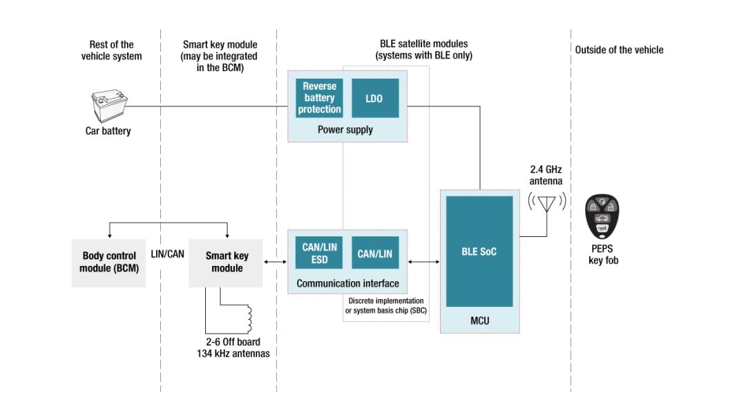
Figure 2: Block Diagram of Automotive PEPS System
Communication Bus Options
Two prominent communication bus architectures in automotive PEPS systems are Local Interconnect Network (LIN) and Controller Area Network (CAN); the Controller Area Network can be either classic CAN or CAN Flexible Data Rate (CAN FD). Both LIN and CAN are widely used standard communication protocols in automotive applications. The maximum baud rate for LIN communication systems is 19.2 Kbps. Classic CAN operates at 1 Mbps, while CAN FD can go up to 5 Mbps.
Both LIN and CAN use message frames as the basis for establishing communication protocols, and both can transmit up to 8 data bytes. A LIN message frame with 8 data bytes has a length of 124 bits, while a standard CAN frame or CAN 2.0 frame (including inter-frame spacing and assuming worst-case bit filling) has a message frame length of 135 bits. Thus, the transmission time for a LIN message frame is 6.46 ms, while a standard CAN message frame is transmitted in just 135 µs.
Choosing Between LIN and CAN
Calculations show that LIN message frames take longer than CAN frames to transmit. Therefore, you might think that faster is better and choose the CAN bus. However, the CAN bus is a dual-wire communication bus, while the LIN bus is a single-wire communication bus. This means that systems based on the CAN bus are more expensive than those using the LIN bus, indicating that the CAN bus may not be the optimal choice.
How do you choose between the two protocols? One approach is to analyze the total number of bytes that need to be transmitted. If the low power Bluetooth chip in the satellite node uses computational algorithms, then the number of bytes to be transmitted will be fewer, making LIN communication sufficient. On the other hand, if the low power Bluetooth chip does not perform any computations and simply transmits all measured raw data, then more bytes will need to be transmitted, requiring a CAN architecture.
Another consideration is power consumption. Typically, LIN bus nodes consume less power than CAN bus nodes in all operating modes. Specific power consumption values can be found in the respective transceiver datasheets.
Example Application
TI’s automotive low power Bluetooth access satellite node reference design demonstrates an application based on a LIN satellite board. This reference design uses TI’s CC2640R2F-Q1 as the low power Bluetooth SoC and TLIN1029-Q1 as the LIN bus transceiver.
When a large amount of data needs to be exchanged between the smart key module and the low power Bluetooth satellite module, classic CAN or CAN FD bus architecture is an obvious choice. You can easily add CAN communication capabilities to the satellite node using TI’s new TCAN4550-Q1 System Basis Chip (SBC), which integrates a CAN FD controller and transceiver. In addition to the integrated controller and transceiver, the SBC also features self-powering capabilities, meaning no additional power supply is needed. The SBC provides a voltage source to power additional components on the printed circuit board and includes a watchdog timer that can be used as a SoC monitor.
Figure 3 shows a satellite node implementation that can fully leverage the capabilities of the TCAN4550-Q1 device.
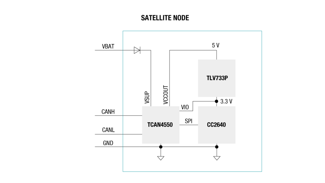
Figure 3: Easily Add CAN Communication Functionality to Satellite Nodes Using TCAN4550-Q1
In Figure 3, the 5V output of the TCAN4550-Q1 is used as the input for the TLV733P-Q1 low input voltage linear regulator. This regulator generates the 3.3V voltage required by the CC2640R2F-Q1 low power Bluetooth SoC, eliminating the need to supply power to the low power Bluetooth SoC from a wide input voltage regulator. Note that the 3.3V regulator output is also used as the VIO for the TCAN4550-Q1, so no voltage level shifter is needed between the low power Bluetooth SoC and TCAN4550-Q1. The watchdog timer in the TCAN4550-Q1 can also monitor the execution of the low power Bluetooth SoC software. Therefore, the highly integrated SBC can provide a cost-optimized solution for low power Bluetooth satellite nodes.
Conclusion
Design engineers are currently implementing next-generation automotive PEPS systems using low power Bluetooth technology. As designers tackle the challenge of determining the optimal number of nodes required to meet PEPS requirements, the communication bus architecture plays a vital role in the solution. Designers can choose between LIN and CAN for communication. TI’s LIN transceivers and the newly launched TCAN4550-Q1 SBC, along with low power Bluetooth SoCs and power management devices, not only provide a complete product portfolio for selection but also allow for flexible optimal solutions tailored for automotive platforms.


Want to learn more about TI interface chips in automotive applications?
Tomorrow from 10 AM to 12 PM
TI experts will provide in-depth analysis!

Live Instructor
Du Anjin, Senior Technical Support Engineer, joined TI in 2006 with over 15 years of experience in high-speed link design support. Currently responsible for technical support for China Auto FPD-Link and Ethernet PHY products.
Live Main Content:
★ CAN/LIN/SBC Automotive Applications
★ FPD-Link Automotive Applications
★ Ethernet PHY Automotive Applications


Click“Read Original”
to register for the July 23rd
TI interface chip automotive application live broadcast.
Give me a little flower on the right