Many friends have left messages on the public account backend regarding applications related to RS485. If you delve deeper into RS485, you will find that there is indeed a lot of knowledge involved. Therefore, we will choose some common issues considered in weak current systems for everyone to understand.
1. What is RS485 Bus?
In industrial sites, it is often necessary to collect multi-point data, analog signals, or switch signals, and RS485 bus is generally used. RS-485 adopts a half-duplex working mode and supports multi-point data communication. The RS-485 bus network topology generally adopts a terminal-matched bus structure, which means using a single bus to connect various nodes in series, and it does not support ring or star networks.
RS485 does not have a specific physical shape and is based on the actual situation of the project. RS485 uses differential signaling with negative logic, where +2V to +6V represents “0” and -6V to -2V represents “1”.
RS485 has two wiring methods: two-wire and four-wire, with the four-wire method only allowing point-to-point communication, which is rarely used today. Currently, the two-wire wiring method is mostly used, which allows a maximum of 32 nodes to be connected on the same bus in a bus topology structure.
The communication distance of the RS485 bus can reach up to 1200 meters.
According to the theoretical structure of the RS485 bus, under ideal conditions, the transmission distance can reach 1200 meters. This condition requires high-quality communication cables, a baud rate of 9600, and only one RS485 device connected to achieve the communication distance of 1200 meters. Therefore, in practice, the actual stable communication distance of the RS485 bus often cannot reach 1200 meters. If multiple RS485 devices are loaded, the cable impedance does not meet standards, the wire gauge is too thin, the converter quality is poor, the equipment has complex lightning protection, and the baud rate increases, all these factors will reduce the communication distance.
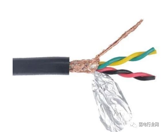
2. RS485 Cables
In general situations, ordinary twisted pair cables are sufficient, while in higher requirement environments, coaxial cables with shielding can be used. When using RS485 interfaces, the maximum allowable cable length for data signal transmission from the RS485 interface to the load is inversely proportional to the baud rate of signal transmission. This length is mainly affected by signal distortion and noise.
Theoretically, the maximum transmission distance of RS485 can reach 1200 meters, but in practical applications, the transmission distance is usually shorter, depending on the surrounding environment. During transmission, using repeaters to amplify the signal can be employed, with a maximum of eight repeaters allowed. This means that theoretically, the maximum transmission distance of RS485 can reach 9.6 kilometers. If long-distance transmission is truly required, fiber optics can be used as the transmission medium, with a photoelectric converter added at both ends. The transmission distance for multimode fiber is 5 to 10 kilometers, while single-mode fiber can reach a transmission distance of up to 50 kilometers.
3. Installation Precautions for RS485 Wiring
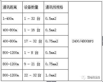
1. What type of communication cable should be used for the RS485 bus?How many devices can be connected on one bus?
Use RVSP shielded twisted pair cables. The specifications of the shielded twisted pair cable used depend on the distance of the 485 communication line and the number of devices connected, as shown in the table below. Using shielded twisted pair cables helps reduce and eliminate the distributed capacitance between the two 485 communication lines and the common-mode interference generated from the surrounding communication lines.
Some say that the RS485 bus can connect up to 128 devices for communication.
However, not all RS485 converters can support 128 devices; it depends on the model of the chip in the RS485 converter and the chip model of the RS485 device, which determines the load capacity based on the lower-rated chip. Generally, the load capacity of RS485 chips has three levels—32 devices, 128 devices, and 256 devices. Moreover, the nominal theoretical values are often not achievable in practice; longer communication distances, higher baud rates, thinner wire gauges, poorer cable quality, inferior converter quality, insufficient power supply for the converter (passive converters), and stronger lightning protection will all reduce the actual load capacity.
Most engineering companies habitually use super category 5 network cables as RS485 communication cables, which is incorrect. This is because:
(1) Ordinary network cables do not have shielding layers and cannot prevent common-mode interference.
(2) Cables with too thin wire gauges cannot be used, as this will reduce transmission distance and the number of devices that can be connected, with at least 0.4mm² or standard network cables recommended.
(3) Network cables are made of solid copper wire, which is more prone to breakage compared to multi-core wires.
2. Why is grounding necessary?
The RS485 transceiver can only function properly within the specified common-mode voltage range of -7V to +12V. Exceeding this range can affect communication, and severe cases may damage the communication interface. Common-mode interference increases the above common-mode voltage. One effective method to eliminate common-mode interference is to use the shielding layer of the 485 communication line as a ground, connecting the ground of devices such as machines and computers in the network together and reliably grounding them.
3. How should RS485 communication lines be routed?
Communication lines should be kept as far away as possible from high-voltage power lines, fluorescent lights, and other sources of interference. If it is unavoidable for communication lines to be near power lines, they should be routed perpendicular to power lines rather than parallel, and should not be bundled together, instead using high-quality twisted pair cables for routing.
4. Why must the RS485 bus use a daisy-chain structure instead of a star structure?
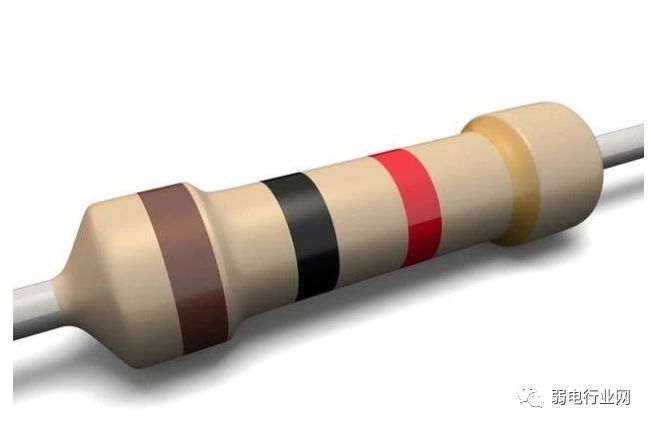
A star structure can cause reflected signals, which can affect RS485 communication. The branch line length from the bus to each terminal device should be kept as short as possible, generally not exceeding 5 meters. If a branch line is not terminated, it will have reflected signals that can strongly interfere with communication, so it should be removed. It is best to connect 120Ω termination resistors at both ends of the RS485 device.
Daisy-chain connection as shown:
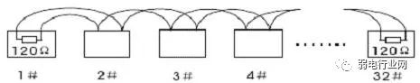
Figure 1
Star connection as shown:
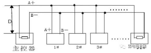
Figure 2
5. Can there be junctions between devices on the RS485 bus?
In the same network system, using the same type of cable, it is advisable to minimize junctions in the lines. Ensure good soldering at junctions, tight wrapping, to avoid looseness and oxidation. Ensure a single, continuous signal path as the bus.
6. What are common-mode interference and differential-mode interference?How to eliminate interference on communication lines?
The 485 communication line consists of two twisted wires, and signals are transmitted through the voltage difference between the two communication lines, hence the term differential voltage transmission. Differential-mode interference occurs between the two signal lines and is symmetrical interference. The method to eliminate differential-mode interference is to add a bias resistor (matching resistor in the camera) in the circuit and use twisted pair cables; common-mode interference occurs between the signal line and ground and is asymmetrical interference. Methods to eliminate common-mode interference include:
(1) Use shielded twisted pair cables and ensure effective grounding.
(2) In strong electric fields, consider using galvanized pipe shielding.
(3) During wiring, keep away from high-voltage lines, and do not bundle high-voltage power lines with signal lines.
(4) Use linear regulated power supplies or high-quality switching power supplies (with ripple interference less than 50mV).
7. Under what circumstances should termination resistors be added on the RS485 bus?
Generally, termination resistors are not needed unless the RS485 communication distance exceeds 300 meters, in which case termination resistors should be added at the start and end of the RS485 communication. Especially when there are fewer devices on the RS485 bus. When there are many devices (e.g., more than 22), termination resistors are usually not needed, as they can reduce the load capacity of the RS485 bus. The connection method for the 120Ω matching resistor at the camera terminal is as follows: The 120Ω matching resistor is set to be disconnected by default when the camera is shipped and can be connected by toggling the 10th bit of the dip switch to ON, and vice versa, if not connected, toggle the 10th bit to OFF.
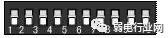
Figure 3
In actual construction, users often adopt star connection methods. In this case, the termination resistors must be connected at the two devices that are farthest apart on the line (as shown in Figure 4, devices 1# and 15#). However, since this connection method does not comply with RS485 industrial standards, it can easily cause signal reflection, reduced anti-interference capability, and other issues, leading to unreliable control signals. The symptoms include the camera being completely uncontrollable or running on its own without stopping.
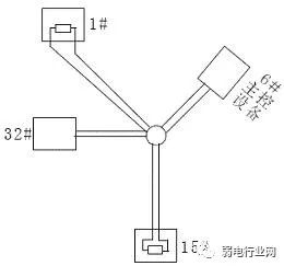
Figure 4
In such cases, it is recommended to use an RS485 distributor. This product can effectively convert star connections into connections that comply with RS485 industrial standards, thereby avoiding problems and enhancing communication reliability, as shown in Figure 5.
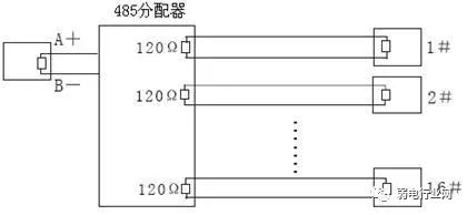
Figure 5
4. Common Faults and Solutions of RS485
1. How to prevent faults from occurring?
To reduce communication faults, the following suggestions are proposed.
1. It is recommended that users use and purchase 485 converters provided by manufacturers or brands recommended by the manufacturer.
2. Manufacturers conduct extensive testing on the 485 converters that match their products and require the manufacturers of the 485 converters to produce and inspect according to fixed performance parameters, ensuring good compatibility with access control devices. Do not be tempted to buy cheap converters from unknown brands.
3. Strictly follow the construction specifications for the RS485 bus to avoid any complacency.
4. For long lines and many loads in RS485 bus projects, adopt scientific and reserved solutions.
5. If the communication distance is too long, such as over 500 meters, consider using repeaters or RS485 HUBs to solve the issue.
6. If the number of loads is excessive, such as over 30 devices on a single bus, it is advisable to use an RS485 HUB to resolve the issue.
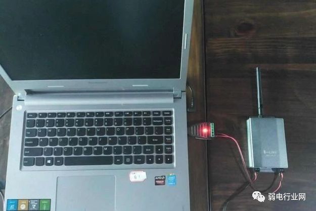
7. Carry all necessary debugging equipment for on-site debugging. Always carry several converters capable of handling long distances and multiple loads, a commonly used laptop, a multimeter for testing circuit breaks, and several 120-ohm termination resistors.
2. What are the common communication faults when using RS485 bus structures?
1. No communication, no response.
2. Data can be uploaded, but not downloaded.
3. During communication, the system prompts interference, or when not communicating, the communication indicator light keeps flashing.
4. Sometimes communication works, sometimes it does not, with some commands working and others not.
3. What debugging methods are available when faults occur?
Before debugging, ensure that the device wiring is correct and that construction complies with specifications. The following debugging methods can be used based on the problems encountered.
1. Common Ground Method:
Connect the GND ground of all 485 devices using one wire or shielded cable to avoid potential differences affecting communication.
2. Termination Resistor Method:
Connect a 120-ohm termination resistor across 485+ and 485- on the last 485 device to improve communication quality.
3. Intermediate Segment Disconnection Method:
Disconnect from the middle to check for excessive device load, long communication distances, or the impact of a specific device on the entire communication line.
4. Separate Line Method:
Pull a separate simple line to the device to rule out wiring issues causing communication faults.
5. Converter Replacement Method:
Carry several converters to rule out whether the quality of the converters is affecting communication quality.
6. Laptop Debugging Method:
Ensure that the laptop you carry is a functioning communication device. Use it to replace the customer’s computer for communication; if it works, it indicates that the customer’s computer serial port may be damaged or malfunctioning.

Weak current industry website: www.rdhyw.com
Latest weak current data update—Weak current intelligent solutions and 5G construction quotes July 7, 2020