Category: Skills Competition
In recent years, both at the national and local levels, conducting vocational skills competitions has become an important measure for cultivating high-skilled talents. Therefore, the performance of students in vocational skills competitions has become a key evaluation indicator for assessing the quality of education and teaching in vocational colleges. Various schools attach great importance to the leading role of skills competitions in talent cultivation, continuously increasing funding, establishing and improving incentive mechanisms, and refining the four-level vocational skills competition system at the national, provincial, municipal, and school levels. They dynamically adjust and revise professional talent cultivation programs based on competition requirements, integrate the demands of competitions into the curriculum system, and incorporate competition projects into teaching projects, striving to achieve a high degree of integration among cultivation programs and job requirements, teaching organization and production processes, teaching content and job tasks, as well as training environments and job realities. By participating in skills competitions, students can not only improve their professional skills and qualities, creating favorable conditions for their successful careers, but also influence and cultivate a large number of students studying in vocational colleges. The author has guided students multiple times in participating in projects such as “Microcontroller Programming and Debugging” competitions, achieving good results, and will introduce this competition project based on the practices of the school.
I. Project Task Preparation
Preparing well before the competition is the foundation for achieving good results. The school must make systematic arrangements around competition work. According to the provincial and municipal student vocational skills competition project notification, the school has established a leadership working group for vocational skills competition projects, responsible for organizing and guiding the competition projects. Each competition project organizes two to three teachers to form a coaching team, responsible for selecting, training, and organizing competition participants. In accordance with the requirements of the competition project and the basic courses already offered, such as “Fundamentals and Applications of Electronic Technology,” “Electronic Circuits,” and “Microcontroller Application Technology (C Language Version),” the coaching team focuses on providing the following training for participants:
1. Circuit design and principle analysis;
2. Using software to draw circuit schematics and PCB designs;
3. Use of common tools and instruments;
4. Debugging, testing, and circuit simulation;
5. Analysis and troubleshooting of common electronic circuit faults;
6. Cultivation of professional and safety awareness.
II. Project Task Content
Familiarity with the competition content and implementing according to task requirements is key to achieving good results. Participants must complete each item according to the task list requirements.
1. Competition Time:
Participants must complete all tasks within 240 minutes.
2. Implementation Content and Requirements:
(1) Complete schematic design according to control requirements
Analyze control requirements, reference the components provided at the competition site, form design ideas, and complete schematic circuit design.
Requirements: The circuit design must be functionally complete and meet technical specifications.
(2) Write microcontroller control program
Write the program based on the schematic circuit design and use Keil software to test the written program.
Requirements: The writing logic should be clear, and the program should run reliably.
(3) Circuit simulation
Use Proteus software to configure the circuit, load the written program, and perform simulation, correcting program errors.
Requirements: Component layout should be reasonable, wiring should be standard, and connections should be correct.
(4) Draw schematic and PCB diagram
Use Protel99sc or Protel DXP to draw schematic and design double-sided PCB.
Requirements: Component layout should be reasonable, wiring should be standard, connections should be correct, facilitating installation, debugging, and maintenance, and files should be named and saved according to the task requirements.
(5) Component identification, selection, and testing
Requirements: Correctly select required components and functional parts from the components provided at the competition site based on the circuit schematic and component list of the provided kit.
(6) Component assembly and soldering
Accurately install the selected components, ensuring reliable connections for plug-in components, and solder components directly onto the printed circuit board.
Requirements: The installation position of components should be correct, with no omissions or errors, fastening should be secure and reliable, the orientation of character markings on components should be consistent, soldering should meet process requirements with no cold solder joints or defects.
(7) Comprehensive circuit debugging
Burn the microcontroller program, debug according to control functions, and check whether the project task functions are normal.
Requirements: Check whether the connections and wiring of the microcontroller and peripheral circuits meet process, safety, and technical requirements. Name and save files according to task requirements.
(8) Safety and professional qualities
Requirements: Attire and operations must comply with safety operating procedures and professional job requirements.
III. Project Scoring Key Points
Understanding the competition scoring rules is an important guarantee to avoid point deductions and losses. In daily teaching and competition coaching, it is essential to supervise students to develop good behavioral habits and competition mentality.
1. Schematic design (5%)
Layout is reasonable, design is standard, connections of the microcontroller and peripheral circuits are correct, and the schematic is complete.
2. Microcontroller program debugging (25%)
According to the designed schematic, load the written program, connect using Proteus, transfer the executable file generated by Keil to Proteus software, and execute the verification program, achieving complete functionality.
3. Drawing schematic and PCB diagram (25%)
Schematic design meets project task requirements, reasonably selects components and connections, correctly indicates parameters of resistors, capacitors, etc., has reasonable and aesthetically pleasing layout, and adheres to PCB design standards.
4. Component identification, selection, and testing (10%)
Reference the component list, accurately count and check the quantity and quality of all assembly materials, correctly use tools and instruments for identification and testing, and correctly select components.
5. Soldering of microcontroller circuit board (20%)
The printed board’s plug-in positions are correct, the polarity of components is correct, the installation and orientation of components and wires should meet process requirements; connections and fastenings should be reliable and secure; there should be no burns or scratches, and the entire machine should be clean without debris; solder joints should be of moderate size, with no cold, false, or bridged solder joints, and solder joints should be smooth, round, clean, and free of burrs; pin processing dimensions and shaping must meet process requirements; wire lengths and stripping lengths must meet process requirements, with intact core wires, and wire ends connected to the designated power pins on the PCB using specified red and black 0.5mm² DuPont wires of 20cm each, connected to the training station’s DC5V power supply.
6. Comprehensive debugging of the microcontroller (15%)
The circuit connections and wiring should be neat, beautiful, and reliable, with reasonable process steps and correct methods, meeting technical and work requirements, detecting correct circuit parameters, and achieving the functional requirements outlined in the task document, completing the report writing.
7. Safety and civility (10%)
High professional qualities, operations must comply with safety operating procedures, not damaging equipment provided at the competition site, not wasting materials, not polluting the competition environment, and avoiding behaviors like leaving tools behind at the competition site that do not comply with professional norms.
IV. Microcontroller Competition Simulation Questions
Design Requirements: Candidates must complete the design and production of a traffic light microcontroller controller within the specified time, using a digital tube to realize the cyclic display output of the digits 0 to 9, completing schematic drawing, simulation debugging, PCB design, component selection, soldering debugging, writing relevant reports, providing product prototypes, and electronic technical documents.
1. Schematic drawing (5 points)
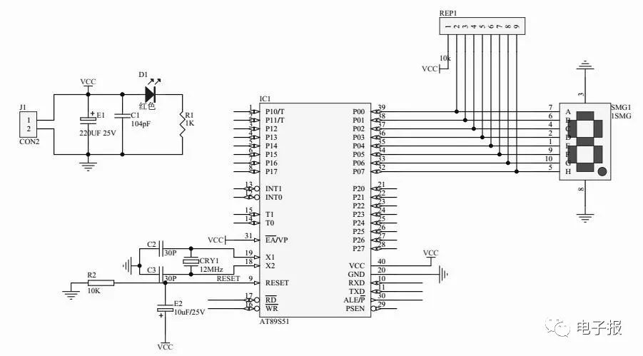
In the given schematic (see Figure 1), draw the connection lines of each component and the microcontroller circuit according to the task requirements.
2. Write microcontroller program (25 points)
Write the microcontroller program according to the introduction of circuit functions. Use the microcontroller’s serial port and the serial input parallel output shift register 74LS164 to expand an 8-bit output channel to drive a digital tube, cyclically displaying the digits 0 to 9 output from the 51 microcontroller’s serial port.
3. Draw schematic and PCB diagram in Protel99sc or Protel DXP software environment (25 points)
Requirements: Create a dedicated exam folder in the root directory of drive E, named: DPJ+Exam Number. All electronic files during the exam must be saved in this folder; if the file path is incorrect, no score will be given. Files include: main file names, project files, workstation numbers. Schematic file should be named sch+XX; schematic component library file slib+XX; PCB file pcb+XX; PCB component packaging library file plib+XX. Here, XX represents the last two digits of the candidate’s workstation number. For example, if the last two digits of the candidate’s workstation number are 96, the schematic file name should be sch96.
(1) Draw complete schematic (10 points)
The IC1(89S51) in the figure can directly use the symbol from the component library 8031. The candidate should indicate their workstation number below the schematic.
(2) Draw PCB circuit board diagram (15 points)
The circuit board size should not exceed 100mm (width) × 80mm (height); layout the microcontroller control and display circuits and buttons in separate areas, with all components placed on the Top layer, signal line width 10mil, VCC line width 20mil, ground line width 30mil; indicate the candidate’s workstation number outside the circuit board boundary.
4. Component identification, selection, and testing (10 points)
(1) Component testing table (8 points)
|
Component |
Identification and Testing Content |
Score Standard |
Score |
|
Digital tube 1 piece |
Determine if the digital tube is common anode or common cathode? |
4 |
Deduct 2 points for each incorrect detection |
|
Electrolytic capacitor 2 pieces |
Test the polarity and quality of the electrolytic capacitor |
Judgment error on 1 item, no score |
|
|
Resistor |
Test the resistance value |
Measurement error exceeding 5%, no score |
(2) Remaining components (resistors, LEDs, crystal oscillators) selected correctly (2 points)
Score deducted from 0.5 to 2 points for incorrect component selection.
5. Soldering of peripheral components on the microcontroller circuit board (20 points)
The competition site provides the microcontroller circuit board, requiring soldering of peripheral components.
(1) Use tools such as diagonal pliers and soldering iron to complete the trimming and soldering of the circuit board, and write a soldering debugging report.
(2) Provide a complete soldered circuit board (10 points)
(3) Assembly and soldering quality (5 points)
Note: For fewer than 10 defects, each defect deducts 0.5 points, and for more than 10 defects, deduct 5 points.
(4) Debugging report (5 points)
6. Comprehensive debugging of the microcontroller (15 points)
(1) After checking the circuit is correct, power on, and the microcontroller should work normally (5 points)
(2) The microcontroller and peripheral circuits work normally according to design requirements (10 points)
7. Safety and civility (professional qualities)
Requirements for the use, maintenance, safety, and civility of tools and equipment. Participants exhibiting any of the following behaviors will have points deducted from their competition scores.
(1) Violating competition rules and operating in advance will be recorded by on-site judges, deducting 5-10 points.
(2) Participants should complete the competition content within the specified time; during the competition, judges will record any violations by each participant, deducting 5-10 points based on the severity.
(3) Minor operational errors that do not result in serious consequences will be recorded by on-site judges, deducting 10 points.
(4) Serious violations or cheating, upon confirmation, will lead to the termination of the participant’s competition by the chief judge, scoring zero.
V. Reference Answers for Microcontroller Simulation Competition Questions
1. Microcontroller and Peripheral Circuit Schematic

Figure 1 Microcontroller and Peripheral Circuit Schematic
2. Microcontroller Control Reference Program
/* Name: Single Digital Tube Cyclic Display 0~9
Description: The loop statement in the main program repeatedly sends the segment codes for 0~9 to port P0, causing the numbers 0~9 to be displayed cyclically
*/
#include
#include
#define uchar unsigned char
#define uint unsigned int
uchar code DSY_CODE[] = {0xc0, 0xf9, 0xa4, 0xb0, 0x99, 0x92, 0x82, 0xf8, 0x80, 0x90, 0xff};
// Delay
void DelayMS(uint x)
{
uchar t;
while (x–) for (t = 0; t < 120; t++);
}
// Main Program
void main()
{
uchar i = 0;
P0 = 0x00;
while (1)
{
P0 = ~DSY_CODE[i];
i = (i + 1) % 10;
DelayMS(300);
}
}
3. PCB Diagram Drawn Using PROTEL Software
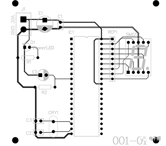
Figure 2 Microcontroller and Peripheral Circuit PCB Diagram
4. Component Identification and Testing Table
|
Component |
Identification and Testing Content |
Score Standard |
Score |
|
Resistor 3 pieces |
Measured value |
Incorrect detection gets no score |
±5% |
|
R1 |
1kΩ |
||
|
R2 |
10kΩ |
Incorrect detection gets no score |
|
|
RP1 |
1kΩ |
||
|
Capacitor 4 pieces |
E1 E2 |
Determine good or bad (indicate your choice with a √ in the box) |
Incorrect detection gets no score |
|
☑ Good □ Bad |
|||
|
Type |
Medium |
||
|
Polypropylene Capacitor (CBB) |
Metalized Polypropylene Film |
||
|
C1 C2 C3 |
Determine good or bad (indicate your choice with a √ in the box) |
Incorrect detection gets no score |
|
|
☑ Good □ Bad |
|||
|
Type |
Medium |
||
|
Ceramic Capacitor |
Ceramic |
||
|
Digital Tube |
Determine polarity (indicate your choice with a √ in the box) |
Incorrect polarity gets no score |
|
|
□ Common Cathode |
☑ Common Anode |
5. Comprehensive Debugging Results
|
Debugging Content |
Technical Requirements |
Score Standard |
Score |
|
Function Achieved |
Display 0 to 9 cyclically on the digital tube from the output of the 51 microcontroller’s serial port. |
1. The power supply section can output 5V DC voltage 2. The crystal oscillator can oscillate normally 3. The digital tube can display from 0 to 9 normally in a loop |
Huarong County Vocational Secondary School, Zhang Zhengjun