
Click the blue text
Bit Time and Bit Synchronization in CAN Communication
-
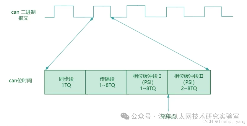
This segment is the first part of the bit time, with a fixed length of 1 time quantum (Time Quantum, TQ). -
It is used to detect edges (level changes) on the CAN bus, from dominant bit (Dominant, logical 0) to recessive bit (Recessive, logical 1), or vice versa. -
By detecting the bit edge, CAN nodes can maintain synchronization with the bus.
-
This segment compensates for the physical delay of the signal from one node to another. The delay is determined by physical factors such as line length and signal propagation speed. -
Its length can be configured, typically ranging from 0 to 8 time quanta.
-
This segment allows for early adjustment of the clock based on the received signal (bit synchronization). If the sampling point is slightly off, this segment can be adjusted for re-synchronization. -
Its length can be configured, usually between 1 and 8 time quanta.
-
This segment is used for delayed adjustment of the clock after sampling. If a signal change is detected on the bus, synchronization recovery can be performed through this segment. -
Its length can be configured, typically between 1 and 8 time quanta.
-
The sampling point is the moment when the bus level is detected within the bit time, usually located at the end of the bit time. -
Bit time is divided into different segments, and the sampling point is usually placed at the end of Phase Segment 1 for optimal signal sampling. -
The choice of sampling point location greatly affects the stability and error rate of CAN communication. The ideal sampling point is typically set between 75% and 87.5% of the bit time.
-
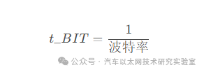
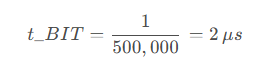
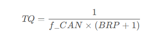
f_CAN: Input clock frequency of the CAN controller. -
BRP (Baud Rate Prescaler): Baud rate prescaler, which can be configured via registers.
Arbitration Rules in CAN Communication
-
When multiple nodes start sending frames simultaneously, they perform bit-level arbitration based on each frame’s Identifier (ID). -
The CAN bus is a wired-AND structure, with two levels on the CAN bus: dominant level (Dominant, logical 0) and recessive level (Recessive, logical 1). The dominant level has a higher priority than the recessive level. -
Each node listens to the bus while sending. If a node detects the bus level as dominant while sending a recessive bit, it knows that it has lost arbitration to another node and immediately stops sending. -
The arbitration process occurs bit by bit until only the node with the highest priority remains to continue sending, while other nodes drop out of the competition and wait for the next idle bus to attempt transmission.
-
After all three nodes start sending SOF, they begin to send their identifiers. -
All nodes’ first bit is 1 (dominant), so they continue sending. -
The second bit is also 0, and all nodes continue sending. -
The third bit is 0, and they continue sending. -
When it comes to the fourth bit, Node A sends 1 (recessive), while Nodes B and C send 0 (dominant). Since dominant has higher priority than recessive, Node A detects the dominant level on the bus and knows it has lost arbitration, thus stopping its transmission. -
Next, Nodes B and C continue arbitration. For the fifth bit, Node B sends 1 (recessive), and Node C sends 1 (recessive), both continue. -
For the sixth bit, Node B sends 0 (dominant), and Node C sends 1 (recessive). Node C detects the dominant level, thus losing arbitration and stopping its transmission.
Error States and Error Detection Mechanisms in CAN Communication
-
A bit error occurs when the data bit sent by a node does not match the actual level on the bus. -
If a node detects the bus as a recessive bit (logical 1) while sending a dominant bit (logical 0), or vice versa, a bit error is triggered. -
Note: During arbitration, nodes may detect different bits but this is not considered an error as it is part of the arbitration mechanism.
-
The CAN protocol requires that after sending five consecutive identical bits, an opposite bit must be inserted as a stuffing bit to ensure synchronization on the bus. -
If a node detects six consecutive identical bits (i.e., no stuffing bit inserted) during reception, a stuff error occurs.
-
The CRC field is used to verify whether the data in the frame has been transmitted correctly. -
The sending node calculates a CRC check value and appends it to the frame. The receiving node recalculates the CRC based on the received frame, and if the result does not match the CRC value in the frame, a CRC error is triggered.
-
Each part of the CAN frame has strict format requirements, including the start bit, control field, data field, CRC field, acknowledgment field (ACK), end bit, etc. -
If any part of the frame does not comply with the required format (for example, if illegal levels appear in the SOF, EOF, or ACK fields), a form error occurs.
-
After the CAN frame transmits data, the receiving node must send a dominant bit in the Acknowledgment Field (ACK Field) to indicate that it has received the data. -
If the sending node does not detect a dominant bit in the ACK slot (ACK slot), it triggers an ACK error.
-
Transmit Error Counter (TEC): Records the number of transmission errors. -
Receive Error Counter (REC): Records the number of reception errors.
-
Initially, all nodes are in the error active state. -
When a node is in this state, it can send active error frames to notify other nodes of the error. An active error frame consists of 6 consecutive dominant bits.
-
When either the transmit error counter or receive error counter exceeds 127, the node enters the error passive state. -
In the error passive state, the node can only send passive error frames, which consist of 6 consecutive recessive bits, and will not affect bus arbitration. -
Nodes in the error passive state do not actively interfere with the bus, preventing impact on the communication of other nodes.
-
If the transmit error counter (TEC) exceeds 255, the node enters the bus off state and stops participating in bus communication. -
Nodes in the bus off state cannot send or receive any messages, but their internal logic continues to operate. This state aims to prevent faulty nodes from continuing to affect other nodes on the bus. -
Nodes in the bus off state need to be reset via software or hardware to restore normal communication.
-
The sending node monitors the bus level in real-time while sending each bit. If it detects that the sent bit does not match the actual bus level, a bit error is triggered. -
The bit monitoring mechanism can effectively detect errors in single bit transmissions.
-
The CAN protocol requires that after sending five consecutive identical bits, an opposite bit must be inserted. The receiving node checks whether this rule has been followed. -
If stuffing bits are not inserted as required, a stuff error is triggered.
-
The receiving node performs format checks on the fixed fields of the CAN frame (such as SOF, EOF, ACK, etc.). If the format does not comply with protocol requirements, a form error is triggered.
-
The CRC field of the CAN frame is used to detect errors in data transmission. The receiving node calculates the CRC value of the data and compares it with the CRC value in the frame. If they do not match, a CRC error is triggered.
-
When the receiving node successfully receives data, it sends a dominant bit in the ACK field. The sending node checks this field, and if no dominant bit is received, an ACK error is triggered.
-
Active Error Frame: Consists of six consecutive dominant bits, indicating a severe error. -
Passive Error Frame: Consists of six consecutive recessive bits, indicating that the node is in an error passive state.


Source: Trump. Yang
*Disclaimer: This article is original or forwarded by the author. If it inadvertently infringes upon any party’s intellectual property rights, please inform us for deletion. The above images and text are sourced from the internet. If there is any infringement, please contact us promptly, and we will delete it within 24 hours. The content of the article reflects the author’s personal views, and the Automotive Ethernet Technology Research Laboratory reprints it solely to convey a different perspective, which does not represent the Automotive Ethernet Technology Research Laboratory’s endorsement or support of that view. If there are any objections, please feel free to contact the Automotive Ethernet Technology Research Laboratory.