Today, I would like to share a comprehensive DIY tutorial: A multifunctional dot matrix clock based on ESP8266.
Introduction
I have known about the ESP8266 for a long time, and I have used it to create some small demos, but I never thought about making something practical, perhaps because I consider myself a novice! Recently, I happened to have some free time at work and thought about setting up an MQTT server to create some IoT-related functionalities.
While browsing forums, I came across a post that caught my attention:
https://www.arduino.cn/thread-98790-1-1.html
This inspired me to create my own dot matrix clock, so I started this journey of making a dot matrix clock step by step. The process was not particularly difficult, but I encountered many issues along the way. Some were resolved, while others had to be dealt with in a straightforward manner. Fortunately, I was ultimately able to achieve the functionalities I envisioned.
I want to share my experiences and lessons with others who have similar interests. My writing may not be great, and my code may not be perfect, but that won’t stop my desire to share.
Demonstration
Image
Video
https://www.bilibili.com/video/BV18i4y1R7ft?spm_id_from=333.999.0.0
Concept
Although many people online have created or are currently working on ESP8266 dot matrix clocks, I feel like repeating this process is akin to reinventing the wheel. As a developer, I also resist the idea of reinventing the wheel.
However, as a beginner, I want to experience the process of creating this wheel, and I hope to incorporate more of my personal ideas into it. Therefore, I decided to start from scratch to create this project.
My personal philosophy is to create a minimalist dot matrix clock that not only has additional functionalities but also meets its core function (timekeeping with low error). Additionally, it should have more features, simpler interactions, and be cost-effective, allowing DIY enthusiasts to create a visually appealing and functional dot matrix clock at minimal cost.
- Simple
- User-friendly
- Feature-rich
- Low-cost
Hardware Selection
Here, I will only introduce some necessary hardware. Those who understand it don’t need me, a novice, to list them. I will also include a Taobao store that I frequently visit: Xinyi Electronics Technology.
This is not an advertisement; the store has a comprehensive range of products at reasonable prices, so you don’t have to switch between different Taobao stores when purchasing items, and the shipping fee is only 3 yuan, while most electronic product stores charge 5-6 yuan. Please look up the specific functions of the components yourself; I won’t elaborate on them.
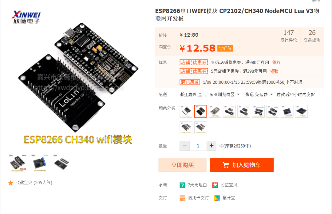
NodeMcu (ESP8266)
This is our core hardware, which has many functions. Perhaps due to the recent price increase of chips, these items are becoming more expensive.
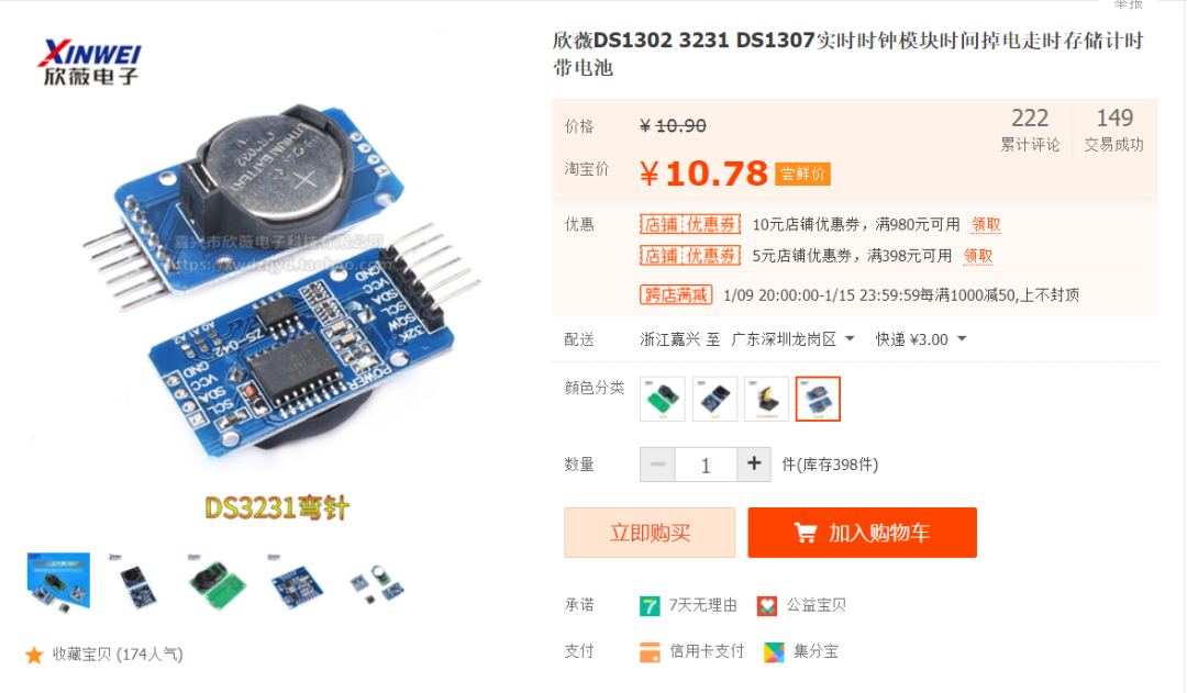
DS3231
The main purpose of buying this module is to maintain time during power outages and to have low time drift.
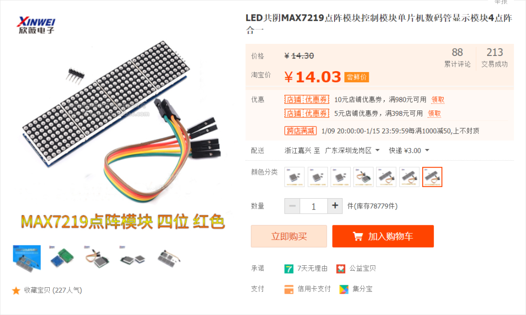
Max7219 32×8 Dot Matrix
There seem to be many driver chips for dot matrices, and one advantage of Max7219 is that it can be cascaded.
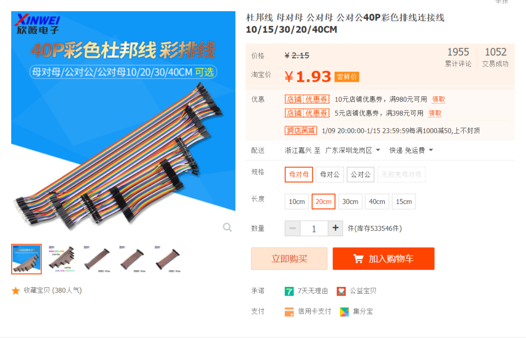
Several Dupont Wires
Buying Dupont wires solves the hassle of soldering, allowing us to quickly and easily create the circuits we need.
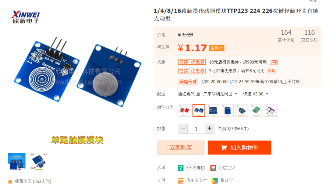
Single-channel Touch Module
This was originally intended for a momentary switch, but that option was also not cheap and had a poor experience. So I bought this touch module to implement single-click, double-click, long-press, etc. Of course, this is not necessary; if you don’t want any physical interaction and only want to interact through the app, you can skip this module.
Clock Functions
Hardware Functions
- NTP Time Synchronization
- Brightness Adjustment
- Display Time
- Display Date
- Display Temperature
- Display Bilibili Follower Count
- Display Custom Content
- OTA Updates
WeChat Mini Program Functions
- Synchronize Device Status
- Set Display Orientation
- Set Brightness
- Set Display Visibility
- Switch Display Content
- Switch Display Mode
- Restore Factory Settings
- WiFi Configuration
- OTA Updates
- Custom Dot Matrix Content
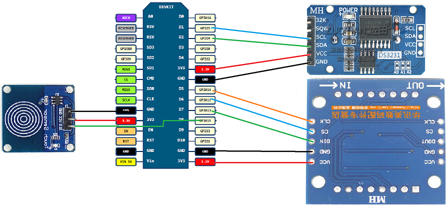
Schematic Diagram
I really lack the talent for drawing and couldn’t find a good drawing tool, so I can only use the built-in Paint tool in Windows to create a simple and understandable schematic diagram. I hope for your understanding.
- PS:
The PCB schematic and PCB board from Lichuang are already in production, with updates to follow.
Production Process
The production process is actually quite simple and can be divided into the following steps:
1. Purchase Components
You can refer to the components mentioned above for purchasing materials; many Taobao stores sell them.
2. Install Corresponding Software
The main software we will use is Arduino, which many DIY enthusiasts should have used. If you have used it, you can skip this section, or you can continue reading.
Install Arduino
Download Arduino IDE from the official website, extract it, and run arduino.exe to complete the installation. The download link is as follows:
https://downloads.arduino.cc/arduino-1.8.19-windows.zip
If the link is invalid, please download it from the official website, selecting the Windows ZIP file option.
Install ESP8266 SDK
I also directly copied this from the forum, but for ease of reading, I will list it below. You can follow the steps I outline. If you encounter any issues, please check here for other solutions.
-
Open the
Arduino IDEmenu > File > Preferences, and in the Additional Board Manager URLs input box, enter the following URL:https://www.arduino.cn/package_esp8266com_index.json -
Download the community-packaged
ESP8266installation package, run it directly, and extract it.
-
SDK Download (44M):
Lancon Cloud sharing link: (recommended)
Aliyun Drive link: (recommended)
Double-click to run to extract. After extraction, open Arduino IDE, and you will find your ESP8266 development board in the Menu --> Tools --> Board.
Note: If you have installed other versions of the ESP8266 SDK, please delete them before using this installation package. To delete, enter %LOCALAPPDATA%/Arduino15/packages in the file manager address bar and press Enter, then delete the esp8266 folder.
Install Serial Driver
NodeMcu comes in many specifications, with the most common being the CP2102 serial chip and the CH340 serial chip, so both require corresponding drivers. Below are the download links for both drivers:
CP2102 Driver
Lancon Cloud sharing link: (recommended)
Blog file link: CP210x_Universal_Windows_Driver.zip (not recommended; use the above link if it is invalid)
CH340 Driver
Lancon Cloud sharing link: (recommended)
Blog file link: CH34x_Install_Windows_v3_4.zip (not recommended; use the above link if it is invalid)
-
Extract the corresponding driver zip file, then double-click to run the driver for your system.
-
After the driver installation is successful, you need to restart your computer.
3. Connect Corresponding Wires
Here, we will use Dupont wires for a simple connection. If any experts are willing, they can solder according to the circuit diagram I drew, but I still recommend using Dupont wires for connection first, and then soldering after debugging the program.
NodeMcu and Max7219 Dot Matrix Wiring
-
VCC → 3.3V (you can also connect to 5V here if you want the dot matrix to be brighter)
-
GND → GND
-
DIN → D7
-
CS → D6
-
CLK → D5
NodeMcu and DS3231 Module Wiring
-
VCC → 3.3V (do not connect to 5V here; lower voltage is safer)
-
GND → GND
-
DIN → D7
-
SDA → D2
-
SCL → D1
NodeMcu and Single-channel Touch Module Wiring
-
VCC → 3.3V (do not connect to 5V here; lower voltage is safer)
-
GND → GND
-
SIG → D8
4. Write the Program
Writing the program using Arduino is actually quite simple, and the general steps are as follows:
Check
-
Check if the ESP8266 SDK is installed successfully.
-
Check if the serial driver is installed successfully.
Install Required Libraries
-
As I am also a beginner, I use many library files created by others and have not rewritten the code based on in-depth principles, so we need to install some library files.
-
The installation steps are as follows:
Tools --> Manage Libraries --> Search for the libraries we need to install --> Click Install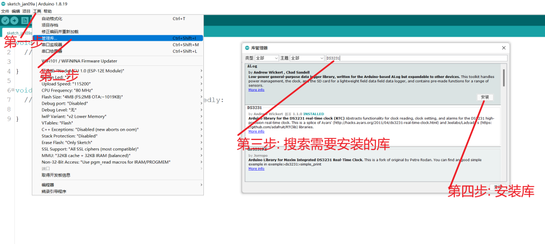
-
The required libraries are as follows:
DS3231DS3231 clock libraryLedControlLibrary for driving the Max7219 dot matrixOneButtonLibrary for implementing single-click, double-click, and long-press functions-
If there are any missing libraries, please check the error messages and install the libraries indicated in the error messages.
Download Source Code
-
GitHubdownload: https://github.com/Lengff/esp8266-lattice-clock-open -
Giteedownload: https://gitee.com/lengff/esp8266-lattice-clock-openDownload our source code from the above links.
Upload Source Code to ESP8266
-
Open the code we downloaded in the previous step using
Arduino IDEFile --> Open --> Select the .ino file in the source code folder -
Select the development board
Tools --> Board --> ESP8266 --> NodeMcu 1.0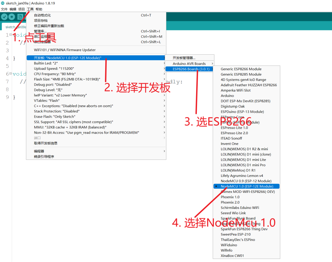
Select Development Board -
Select the port
Tools --> Port --> Select the port corresponding to our serial device -
Upload the program
Project --> Uploadorclick the left arrow(set baud rate to 115200 for faster uploads)
5. Testing & Verification
Here are some common issues I encountered during the process:
-
Program compilation failed
-
The most common reason for compilation failure is that the library files are missing or there is an issue with the installation of the ESP8266 SDK. Check the error messages in the compilation output.
Program upload failed
-
Upload failure is usually due to the wrong port selection or the wrong development board selection.
No display after successful upload
-
You need to check if your wiring is correct. (Please perform this operation after disconnecting the power.)
One-click network configuration unsuccessful
-
Network configuration requires the phone and device to be on the same WiFi network, and the WiFi must be 2.4G.
-
Check the dot matrix display content:
no wifiindicates that WiFi has not been configured;con wifiindicates that WiFi information has been configured and is attempting to connect. If you need to reconfigure WiFi, you must long-press the touch button for 6 seconds to reset the system. -
It is recommended to press the reset button on the
NodeMcubefore clicking the network configuration on the phone.
After successful network configuration, the displayed content is 23:59:59
-
This indicates that there is an issue with the wiring of the DS3231. You need to check if the wiring is correct. (Please perform this operation after disconnecting the power.)
-
If it still doesn’t work, please disconnect the power, remove the battery from the DS3231, reinstall it, and try again.
Interaction
We have set up a touch button for human-computer interaction, and more interaction logic is implemented in the mini program.
Touch Button:
-
Single-click: Single-click switches the display function, currently cycling through
Time - Date - Temperature - Bilibili Follower Count - Custom Display. -
Double-click: Double-click switches the display mode of the function. For example, the time has two display modes: 1.
Hour - Minute - Second2.Hour - Minute, allowing for two different display modes. -
Long press for three seconds: Long pressing for more than three seconds but less than six seconds will trigger NTP automatic time calibration.
-
Long press for six seconds: Long pressing for more than six seconds will reset the system (needed when the system is malfunctioning or when the WiFi has changed).
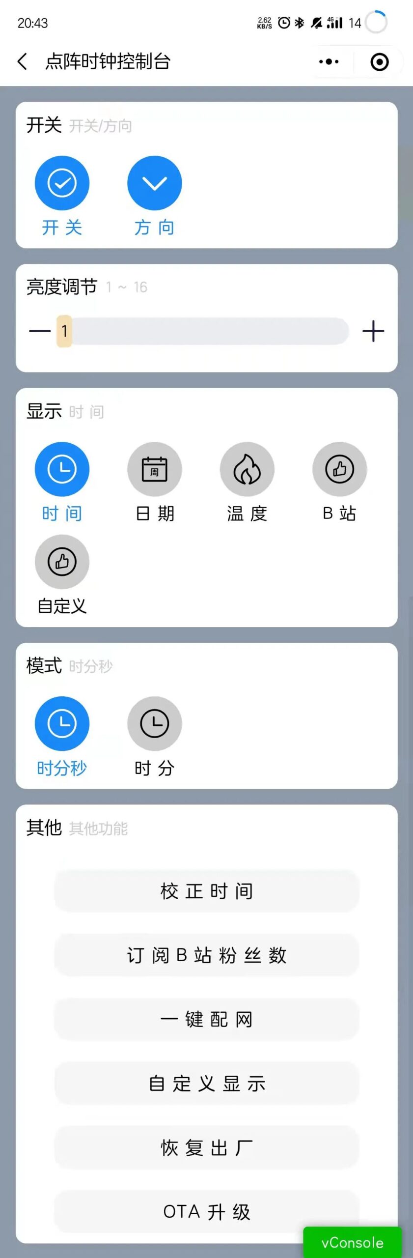
WeChat Mini Program:
-
I won’t elaborate too much here; the functions in the WeChat mini program are quite simple and straightforward. All the functions supported by the above buttons are also supported by the WeChat mini program.
Mini Program
Why did I choose a mini program to interact with the ESP8266?
-
Mini programs are relatively quick to develop, support many functions, and many features can be directly called via APIs.
-
Using an app or accessing the page within the ESP8266 feels a bit cumbersome for interaction. I believe interaction should be as simple as possible, without excessive learning costs.
-
Mini programs support network configuration, UDP, Bluetooth, and many other functions. Future projects may also utilize mini programs.
Page Display
Code
Currently, the mini program is not included in this open-source sharing. In fact, the mini program is not very difficult to develop and can be used directly, reducing the development workload for everyone.
Mini Program Access
You can find my mini program by scanning the QR code below or searching for the mini program Lengff in WeChat.

Communication Method
Currently, the communication between the ESP8266 and the mini program uses UDP communication. The advantage of using UDP is that it is connectionless, meaning it can be used immediately without the need for a server.
As long as the ESP8266 and the phone are connected to the same local area network, the device can be discovered via broadcast without establishing a long connection. The downside is that it is unstable and may lose packets, but I believe this is acceptable since the phone mainly sends commands. By sending each command twice, the probability of packet loss decreases.
Transmission Protocol
UDP is used to send hex data packets for data transmission between the ESP8266 and the phone, so I have defined a simple custom UDP transmission protocol as follows:
Custom UPD protocol for UDP communication between the mini program and ESP8266

|0 1|2 3 4 5|6 7|0 1 2 3 4 5 6 7|
---------------------------------
|RT |TE     |VN | LH            |
---------------------------------
Message Data (64bit)
---------------------------------

Custom UDP Protocol Description:

1. RT: (2bit) Success return value
2. TE: (4bit) Type of message: 0: Reset time, 1: Set brightness, 2: Switch function, 3: Switch function display style, 4: Subscribe to Bilibili UID, 5: Enable dot matrix screen, 6: Switch display orientation, 7: Set user data, 8: Set animation speed, 9: OTA upgrade (there is a limitation here, supporting a maximum of 16 types, so this will be expanded in the future)
3. VN: (2bit) Version of the protocol, currently fixed at 1
4. LH: (8bit) Length of the data packet
5. Message Data: (64)bit The maximum data packet length supported by version 1 is 64bit
Optimization?
There is certainly room for optimization. The changes are not significant; the goal is to connect to my own MQTT server while also being compatible with UDP communication. However, I have not done this yet because I currently do not have a stable and usable server. Blindly connecting could affect the normal functionality of the device during future upgrades.
Self-Evaluation
This project (which can also be considered a small project) took me over a month. It cannot be said that I started from scratch; I was somewhat familiar with some things at the beginning, but my knowledge was scattered, like a pile of disorganized puzzle pieces. This time, it felt like I was piecing together a puzzle.
Although the result is not perfect, I have managed to create a project. While many people have created similar dot matrix clocks, I personally believe that engaging in the practice reveals that it is not as simple as it seems. Moreover, you may not be satisfied with what others have done; creating your own allows you to inject your own soul into it.
Here are my personal reflections: I am not a professional in hardware development; this is just a personal hobby. Although I have accumulated some related knowledge, it is far less efficient than systematic learning.
Therefore, if you really want to learn this, you should systematically watch some videos to learn, and then practice. Although I have mastered some scattered skills, I do not know how to apply them, so I need to continuously practice to understand the skills I have acquired.
Disadvantages:
- Requires a WiFi connection (must be 2.4G WiFi) to function – (this will be optimized in future programs)
- Requires continuous power supply, as the dot matrix consumes a lot of power, so using batteries results in a poor experience.
Advantages:
- Supports OTA for continuous system updates
- Simple and convenient interaction
- Supports custom display content
Conclusion
Here, I provide an 8x8 and 32x8 dot matrix online pattern tool, which is quite rough. If there are areas for improvement, please feel free to leave comments.
8×8 dot matrix online pattern tool: http://lengff.com/lengff/lattice2.html
32×8 dot matrix online pattern tool: http://lengff.com/lengff/lattice3.html
ENDAuthor: LengffSource: Embedded MiscellanyCopyright belongs to the original author. If there is any infringement, please contact for removal.▍Recommended ReadingDomestic MCU manufacturers are also starting to compete…Beginner’s Tutorial: A Step-by-Step Guide to Writing an Android AppTo become an embedded expert, you can’t miss these 100+ open-source hardware and software projects!→ Follow for more updates ←