PLC Serial Communication: Modbus Protocol Analysis and Implementation
In actual industrial automation projects, communication between PLCs and other devices (such as sensors, inverters, HMIs, etc.) is an indispensable part. Among the many communication protocols, Modbus protocol has become a “frequent guest” in the field of industrial control due to its simplicity, ease of use, and strong openness. In this article, we will discuss PLC serial communication, focusing on the basic principles, implementation methods, and practical applications of the Modbus protocol, and guide you through practical operations with code and ladder diagrams.
What is Modbus Protocol?
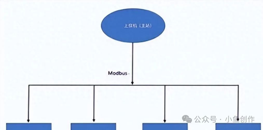
Let’s start with a simple analogy: among industrial devices, the Modbus protocol is like “Mandarin”; no matter which manufacturer the device comes from, as long as it supports the Modbus protocol, everyone can “communicate”. It is mainly used for master-slave communication, where the PLC acts as the master station (Master) and exchanges data with multiple slave devices (Slave) through the serial port.
Basic Concepts
-
Master Station (Master): Responsible for initiating communication requests, such as PLC.
-
Slave Station (Slave): Responds to the master station’s requests, such as sensors, inverters, etc.
-
Registers: “Cells” used to store data; the Modbus protocol specifies four common types of registers:
-
Coil (Coil, 0x): Stores binary data (on/off state).
-
Discrete Input (Discrete Input, 1x): Read-only binary data.
-
Holding Register (Holding Register, 4x): Stores analog or integer data, both readable and writable.
-
Input Register (Input Register, 3x): Read-only analog data.
Note: In the Modbus protocol, addresses start from 1, but many PLC software display them starting from 0, which can easily cause confusion! For example, Modbus address 40001 may be displayed as 40000 in PLC.
Communication Process of Modbus RTU and PLC
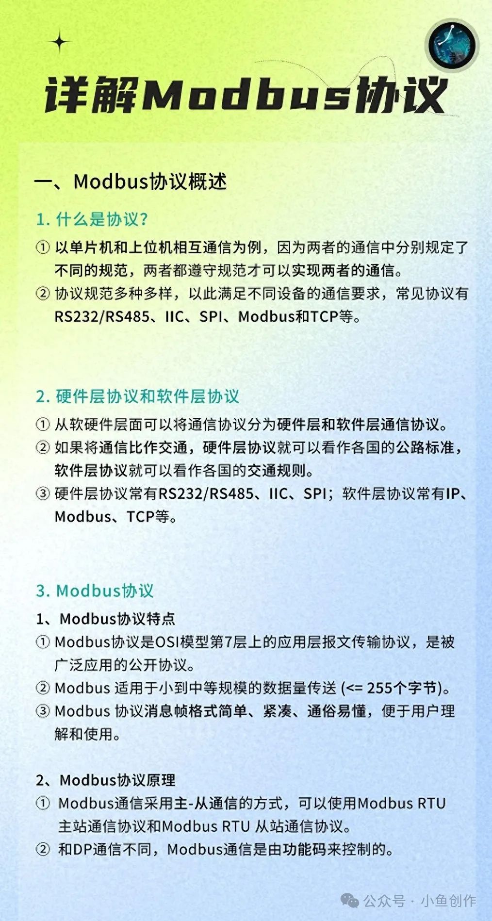
There are two common implementations of the Modbus protocol: **RTU (serial communication) *and* TCP (Ethernet communication)**. This article focuses on *Modbus RTU* because it is more common in small automation projects.
The communication process of Modbus RTU can be simply described as:
-
Master Sends Request: The PLC sends a request frame with an address and function code.
-
Slave Responds: The target device receives the request and returns data or performs actions based on the function code.
-
Verification and Error Handling: Ensures reliable communication through CRC verification.
Hardware Connection and Circuit Diagram
In Modbus RTU, the commonly used physical interface is RS-485, which supports multi-device communication and can connect up to 32 devices, with strong anti-interference capability.
Wiring Method
-
RS-485 Interface: Two signal lines A and B.
-
A (+): Positive
-
B (-): Negative
Termination Resistor: To avoid signal reflection, it is recommended to connect a 120Ω termination resistor at both ends of the communication bus.
Wiring Diagram Example
1 PLC (Master)           Slave 1             Slave 2
2     A ---------------- A --------------- A
3     B ---------------- B --------------- B
Note:
-
The A and B wires must not be reversed; otherwise, communication will fail.
-
When communicating with multiple devices, ensure that all devices have the same baud rate and parity settings.
PLC Programming Implementation: Modbus Read/Write Holding Register
Below is a common application example: the PLC reads temperature data (holding register) from a sensor via Modbus and controls a relay.
PLC Ladder Logic
In PLC programming software, we usually use function blocks (Function Block) to implement Modbus communication, such as Siemens PLC’s MB_COMM_LOAD and MB_MASTER function blocks.
Core Logic
-
Initialize Communication Parameters: Set baud rate, device address, etc.
-
Send Read Command: The master sends a request to read the holding register.
-
Receive Response Data: Store the temperature data in the PLC’s register.
-
Logical Judgment: If the temperature exceeds the threshold, control the relay action.
Ladder Diagram Example
Here is a simple logic:

-
Read the value of the holding register 40001 (temperature data) from the device at slave address 1.
-
If the temperature value > 50, turn off relay 0.
[Initialize] —–> [Send Modbus Read Command] —–> [Receive Data] —–> [Judge Temperature Value] —–> [Control Relay]
Common Modbus Function Codes and Frame Format
The frame format of Modbus RTU is as follows:
| Field | Length (bytes) | Description |
|---|---|---|
| Slave Address | 1 | Address of the target device |
| Function Code | 1 | Type of operation performed |
| Data | N | Content of the operation data |
| CRC Check Code | 2 | Check if the data is correct |
Common function codes:
-
0x03: Read Holding Register
-
0x06: Write Single Holding Register
-
0x10: Write Multiple Holding Registers
Practical Application Case: Temperature and Humidity Collection and Alarm
Background
A factory needs to monitor the temperature and humidity in the workshop in real time, using a PLC to read data from a temperature and humidity sensor with an RS-485 interface, and automatically control a fan and humidifier based on the temperature and humidity.
Implementation Steps
-
Hardware Selection:
-
The temperature and humidity sensor supports Modbus RTU protocol, with device address 1.
-
The temperature value is stored in holding register 40001, and the humidity value is stored in 40002.
-
PLC Programming:
-
Read data from 40001 and 40002.
-
If the temperature > 30°C, start the fan.
-
If the humidity < 40%, start the humidifier.
Ladder Diagram Implementation
-
Use function blocks to read holding registers 40001 (temperature) and 40002 (humidity).
-
Compare the temperature and humidity values to control output points Q0.0 (fan) and Q0.1 (humidifier).
[Temperature > 30] —–> [Q0.0 = 1] (Fan Starts) [Humidity < 40] —–> [Q0.1 = 1] (Humidifier Starts)
Common Problems and Solutions
-
Communication Failure, No Data Read?
-
Check if the baud rate, address, and function code are consistent.
-
Check if the RS-485 wiring is correct and if termination resistors are connected.
-
Incorrect Data Read?
-
Confirm if the register address is correct.
-
Pay attention to the data format (16-bit unsigned integer, floating-point, etc.).
-
Data Loss During Multi-Slave Communication?
-
Ensure the master polling interval is long enough to avoid frames being sent too closely together.
Practical Exercise Recommendations
-
Hardware Preparation: Use a PLC that supports RS-485 and a sensor that supports Modbus RTU to set up a communication environment.
-
Basic Experiment: Attempt to read the values of the holding registers and view the results through the PLC’s register monitoring window.
-
Extended Exercises: Add multiple slave devices to implement multi-device data collection.
Through the study of this article, you should have mastered the basic application skills of PLC serial communication and the Modbus protocol. Although communication may seem small, it is a “big deal” in industrial automation; mastering it will help you avoid pitfalls in your projects!