
Back in June 2012, I introduced the first Surface brand tablet laptop launched by Microsoft, which included two types: x86 architecture (Surface Pro) and Arm architecture (Surface RT). A week later, I compared these two different versions. Two years later, I purchased refurbished units of both models for subsequent use (and of course, as material for my articles).
My first-generation Surface Pro has been working for almost ten years now, at least the last time I checked it. I upgraded it from Windows 8 to 8.1, and recently to Windows 10; each upgrade was tedious and imperfect. Now I have put it away, as I switched to using the Surface Pro 4 and LTE-enhanced Pro 5 successors for my daily laptop.
As for that Surface RT (more accurately, the Windows RT version of Surface), I could have disassembled it long ago (Figure 1).
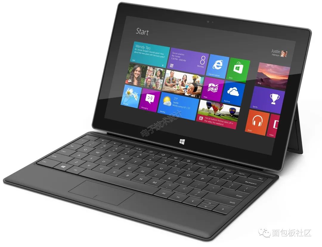
Figure 1: Microsoft Surface with Windows RT operating system.
I mentioned in my May 2017 article “Microsoft’s hardware support burden” that the Surface RT had stopped responding to the power button back in August 2015, so I placed it among the devices to be disassembled. However, I would still check it occasionally to see if it would recover on its own. Although Windows RT 8.1 can still enjoy more than two years of extended technical support from Microsoft, subsequent software development has stopped (worse still, you can only install applications from the Microsoft Store unless you jailbreak it). While my Kindle was fixed by replacing the battery, I believe the root of the Surface RT’s problem is not the battery (I have already found out how to replace the Surface RT battery), because it cannot start even when plugged into AC power. From the indicator light at the back of the adapter, the AC adapter itself is functioning normally (Figure 2).
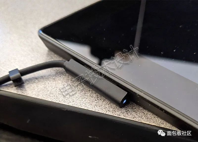
Figure 2: The AC adapter for the Surface RT is working normally.
So, I decided to disassemble this Surface RT. First, as before, I compared its dimensions with a 19.1mm diameter 1-cent coin. The dimensions of this tablet laptop are 274.60mm × 172.00mm × 9.30mm, weighing 680.40 grams. The optional touch cover and type cover keyboard are not shown here, as they can be used with my first-generation Surface Pro, so I do not intend to modify them.
Above the 1366×768 pixel HD display is a 720p front camera, and the corresponding rear camera matches the resolution of the front camera, located in the middle of a plastic strip on the back of the Surface RT (Figure 3). Every time I see the plastic strip, it makes me think there should be an RF antenna underneath (we’ll check that later).
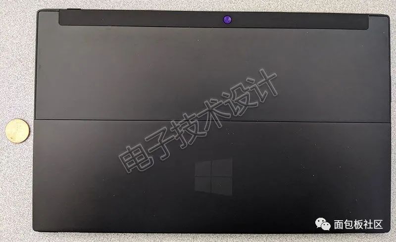
Figure 3: Size comparison of the Surface RT with a 19.1mm diameter 1-cent coin. The camera is above the display.
Open the kickstand (which only has one angle, while the kickstand position of its successors can be adjusted flexibly), and stand the Surface RT up to see the ports on the right side, from top to bottom: speakers, proprietary digital A/V, full-size USB 2.0, microSDXC (below the kickstand), and magnetic power connector (Figure 4).
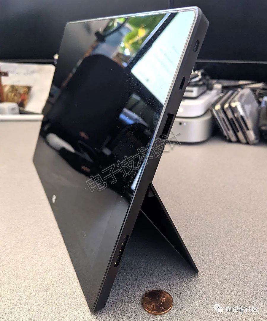
Figure 4: Ports on the right side of the Surface RT.
The ports on the left side of the device include speakers, a 3.5mm headphone/microphone jack, and volume up/down buttons (Figure 5).
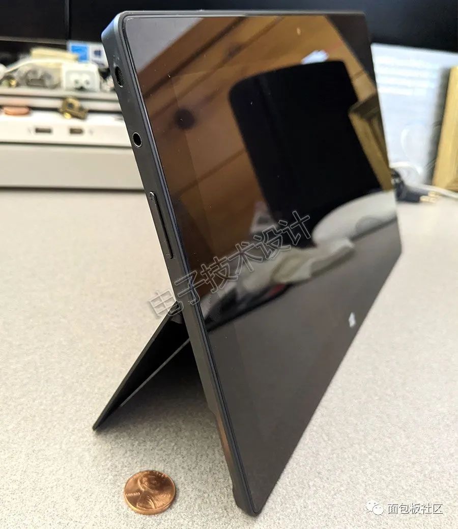
Figure 5: Ports on the left side of the Surface RT.
Now it’s time to delve into the Surface RT. The first step is to remove the kickstand. Open the kickstand, and you can see a set of product markings on the back of the main unit beneath the kickstand (the magnetic keyboard connector is also visible in the photo), as shown in Figure 6.
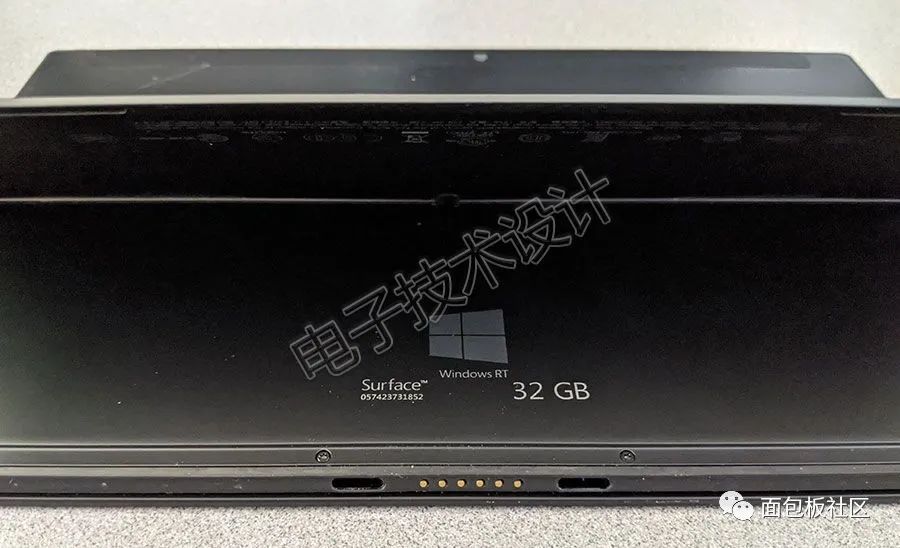
Figure 6: A set of product markings on the back of the Surface RT main unit.
Each hinge connection between the kickstand and the main unit has a T5 Torx screw, which needs to be removed (Figure 7).
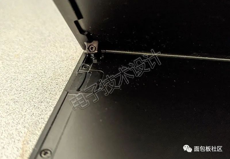
Figure 7: Each hinge connection between the kickstand and the main unit has a T5 Torx screw.
After removing the kickstand, there may be more product markings underneath it. Some meaningful information includes:
-
Model: 1516
-
FCC ID: C3K1516
-
Input Voltage: 12V/2.0A
Figure 8 shows the microSD card mentioned above, which I plan to keep, as it may be useful later.
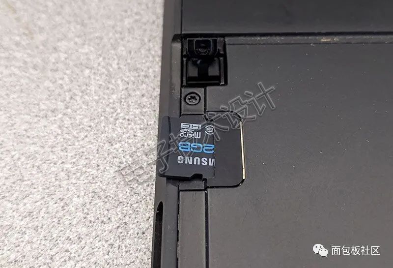
Figure 8: microSD card.
Now let’s disassemble that plastic strip. Some people who have disassembled the Surface RT before said that it should pop right out with a pry tool, but mine did not pop out. Perhaps because my tablet is a refurbished device, stronger adhesive was used to secure it, or maybe it’s because I’m not skilled enough.
Figure 9 shows the top and bottom of the removed plastic strip, as well as a close-up of the rear camera (with an ambient light sensor hole next to it) and a microphone opening.
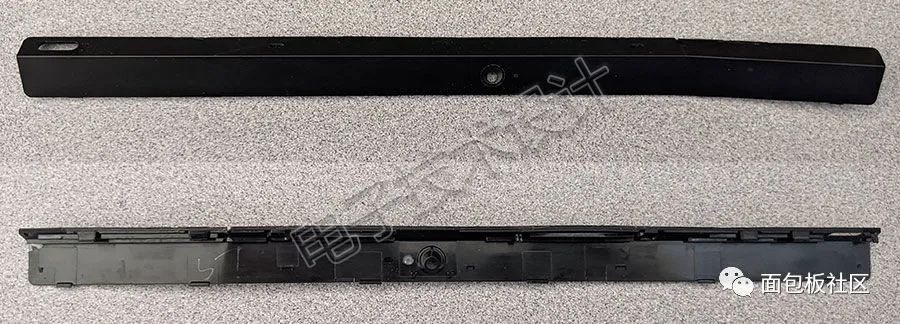
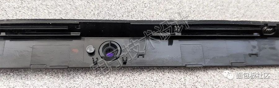
Figure 9: Top and bottom of the plastic strip.
Figure 10 shows the back of the main unit after the plastic strip has been removed, giving a rough glimpse of the internals. Note that here you can see the rear camera and ambient light sensor as well as the rubber “vent holes” for the MEMS microphone, but the antenna is not visible; however, trust me, they must be inside.
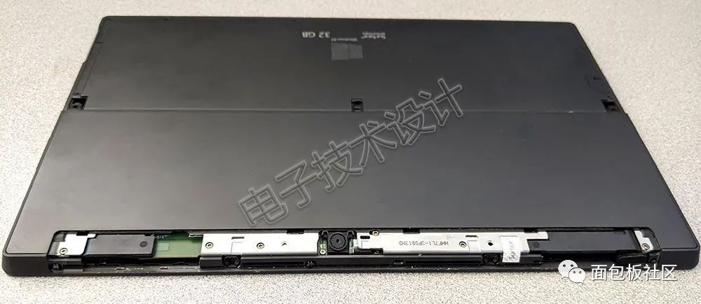
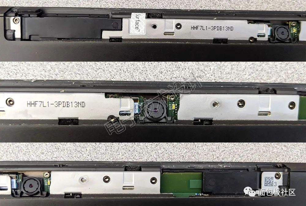
Figure 10: Back of the main unit after the plastic strip has been removed.
Next, I need to unscrew the 17 T5 Torx screws around, one of which is under the warranty sticker (if you tear this sticker, you won’t be able to enjoy the warranty) (Figure 11).
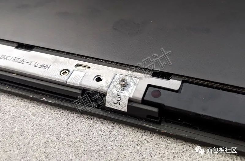
Figure 11: Unscrewing the 17 T5 Torx screws.
After unscrewing all the screws, the two halves of the main unit can be separated (Figure 12). Can you see the special part right away?
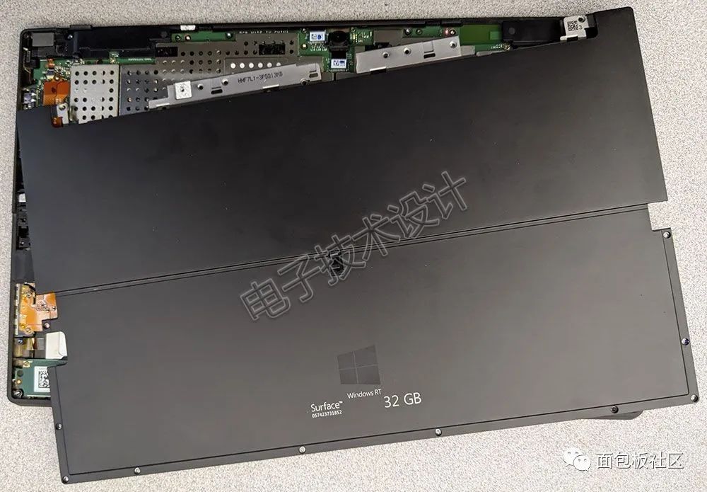
Figure 12: After unscrewing all the screws, the two halves of the main unit can be separated.
Get closer; can you see that glowing thing (Figure 13)?
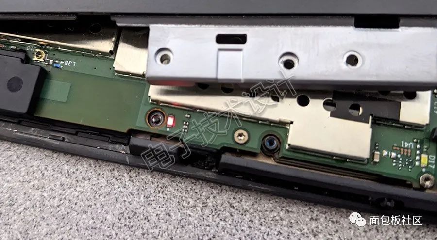
Figure 13: After unscrewing all the screws, a glowing component can be seen.
Before disassembling the Surface RT, I made one last attempt to charge it to see if it would start. This light proved my thoughts were correct: the battery is not the root cause of the system failure. Of course, illuminating a small LED light requires much less power than powering the entire computer.
Separate the two halves of the main unit (Figure 14).
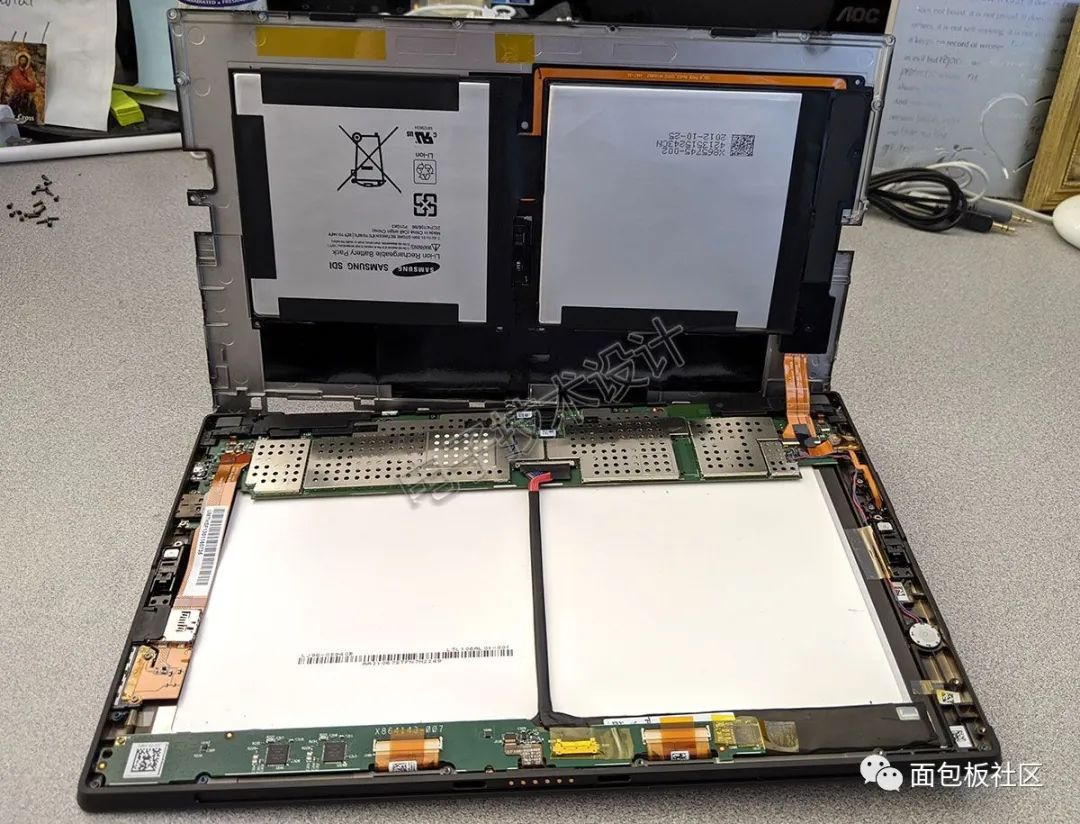
Figure 14: Separating the two halves of the main unit.
Next, remember that the battery subsystem is located in the half of the main unit on the back, while the front half contains the motherboard, LCD, etc. This also means that when you see a circuit board on the left side of a picture, the connector associated with it is located on the right side when viewed from the front of the main unit.
Speaking of which, let’s take a closer look at the battery subsystem. It consists of two batteries connected to the rest of the system via a flexible PCB cable (the upper part of Figure 14).
It is clear that the battery subsystem consists of two distinct lithium-ion polymer batteries rated at 31.5Wh, providing a combined voltage of 7.4V.
Now, looking at the other half, at first glance, it looks somewhat similar to the previous half, but it is actually much more interesting (the lower part of Figure 14). This half also contains two roughly square white areas, which are the backlight system for the Samsung LTL106AL01-002 display.
All components in this part are secured with plastic clips and T3/T4 Torx screws, which can usually be easily handled with my iFixit 64-bit tool set. First, remove the charging connector and the microSDXC reader from the right-side component (remember, corresponding to the left side of the photo) (Figure 15).
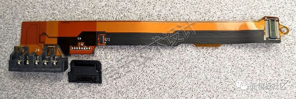
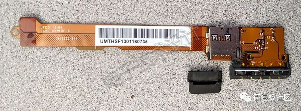
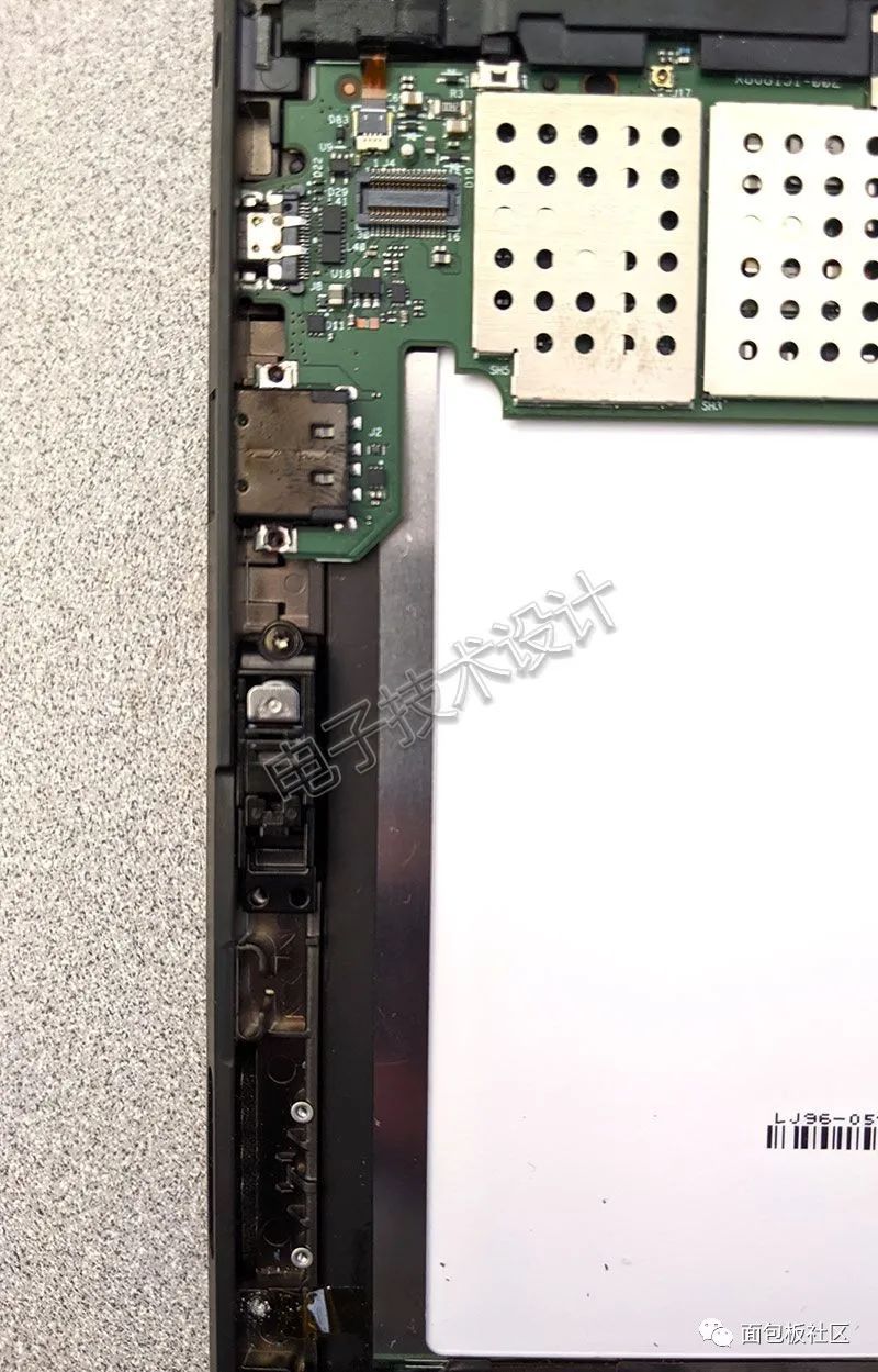
Figure 15: Removing the charging connector and microSDXC reader.
Above it are the right-side speaker and power switch components. After removing them, you can see more clearly how the sensors communicate with the outside (Figure 16).
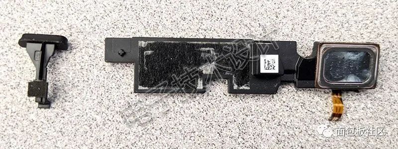
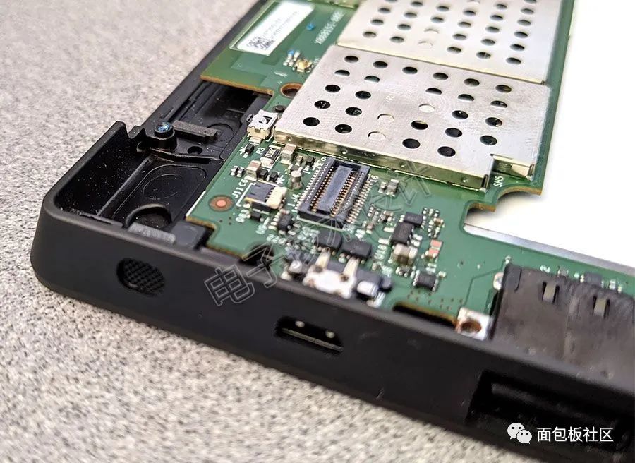
Figure 16: Removing the right-side speaker and power switch components.
Then remove the corresponding left-side speaker (Figure 17).
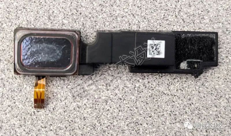
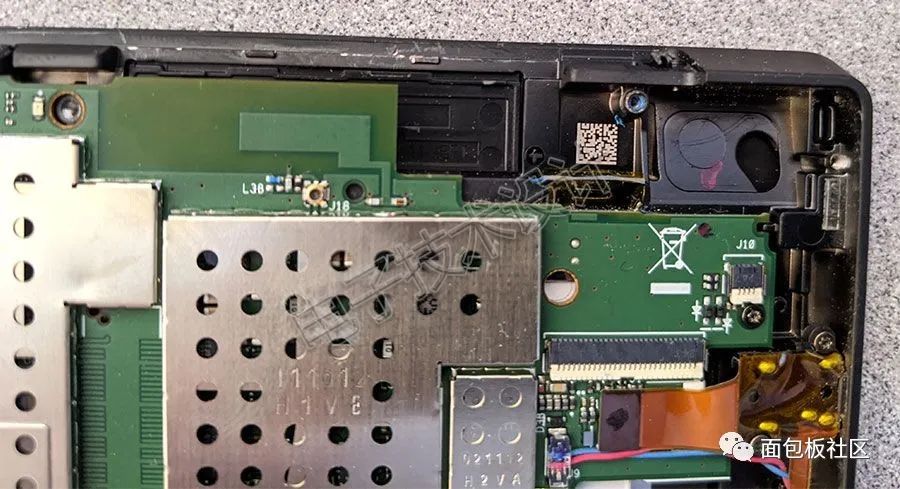
Figure 17: Removing the left-side speaker.
Figure 18 shows the 3.5mm headphone/microphone jack and volume control component.
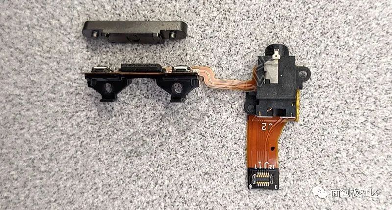
Figure 18: 3.5mm headphone/microphone jack and volume control component.
As for the component below it (Figure 19), previous disassemblers of the Surface RT strangely thought it was a third speaker, but I am sure this is a button cell battery used to maintain system settings when the main battery is dead (do you agree with me?).
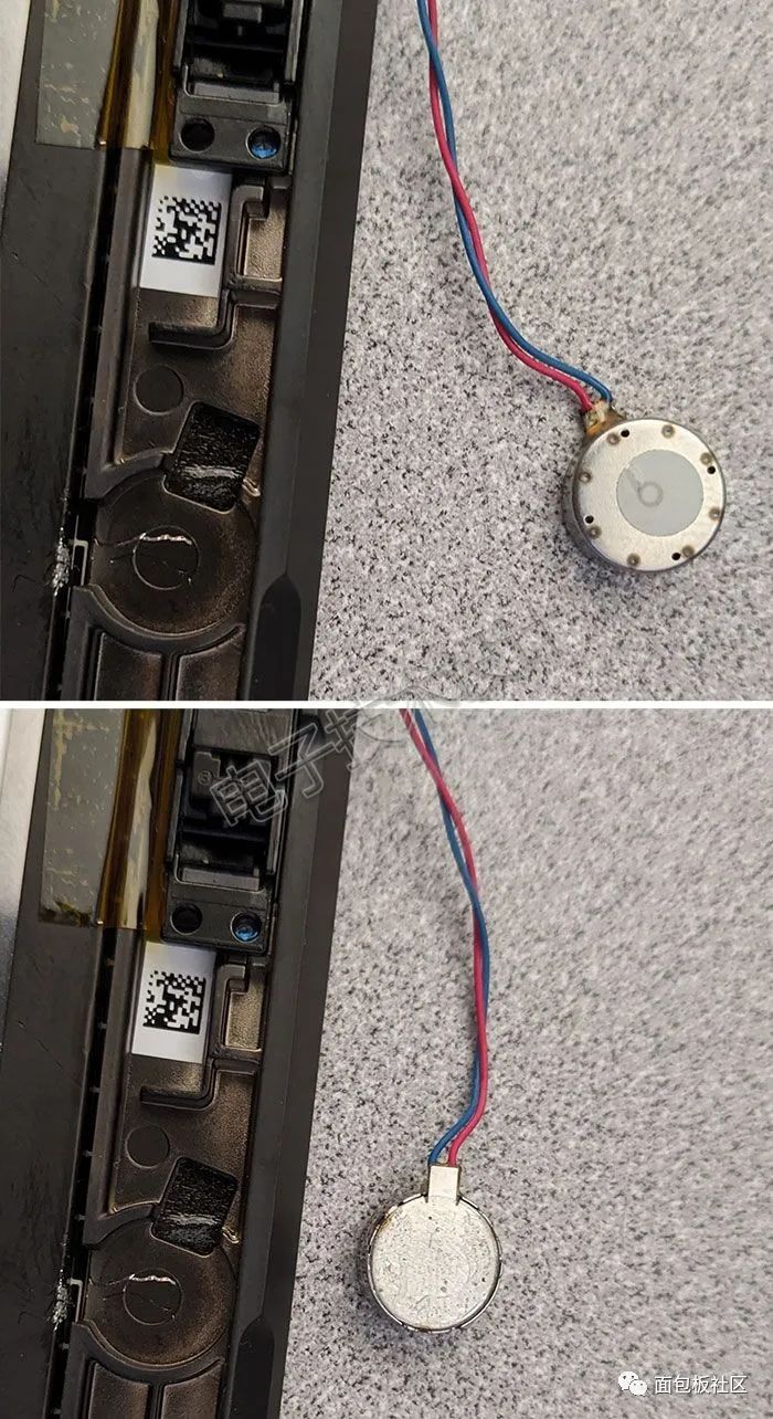
Figure 19: The button cell battery is used to maintain system settings when the main battery is dead.
At the bottom is the touchscreen controller PCB, as shown in Figure 20. The first image has three Atmel (now Microchip Technology) mXT154 touch controllers from ICs, matching with the Atmel mXT1386 touchscreen main controller SoC on the other side.
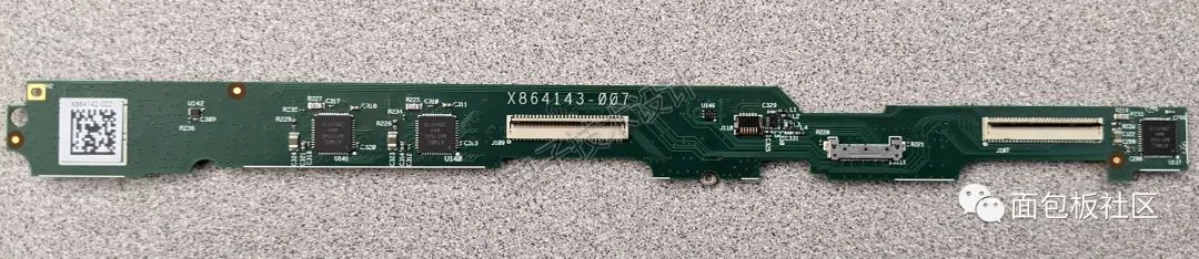
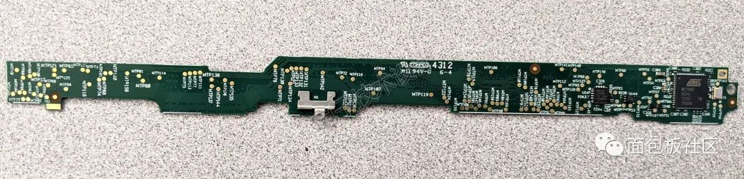
Figure 20: Touchscreen controller PCB.
Figure 21 shows the remaining parts after removing this PCB.
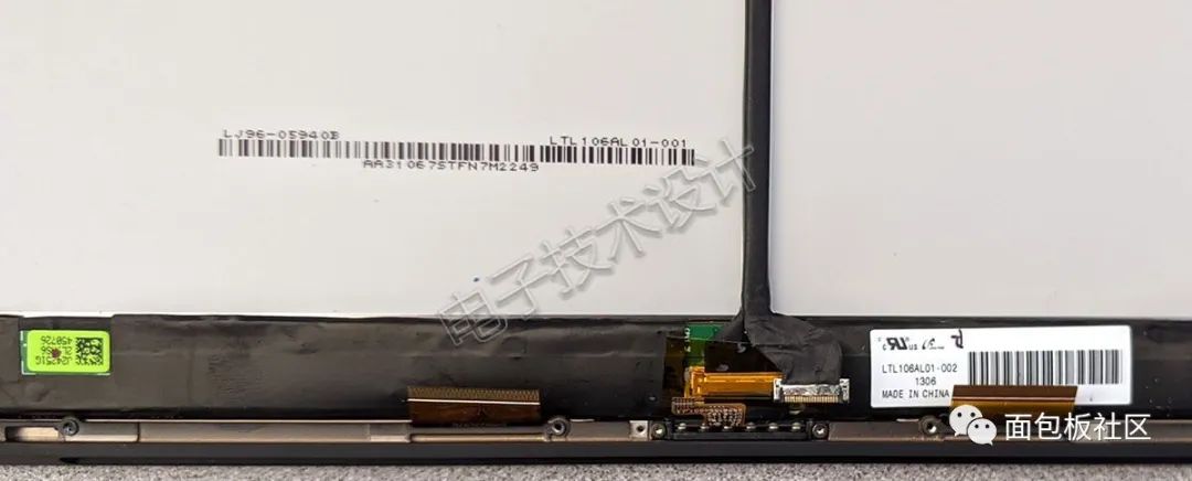
Figure 21: Removing the touchscreen controller PCB from the main unit.
Did you notice that I left the most exciting part (maybe some would disagree) for last? Isn’t it fun? Finally, we can take a look at the top side of the motherboard and the remaining parts after removing this section (Figure 22).
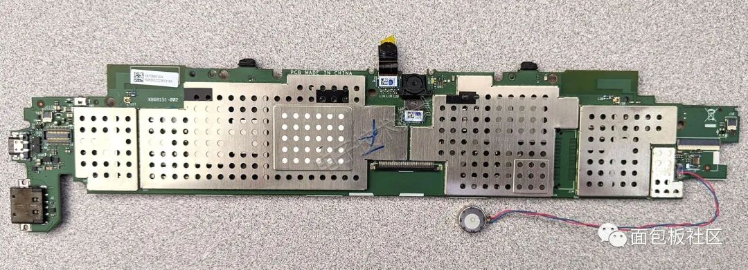
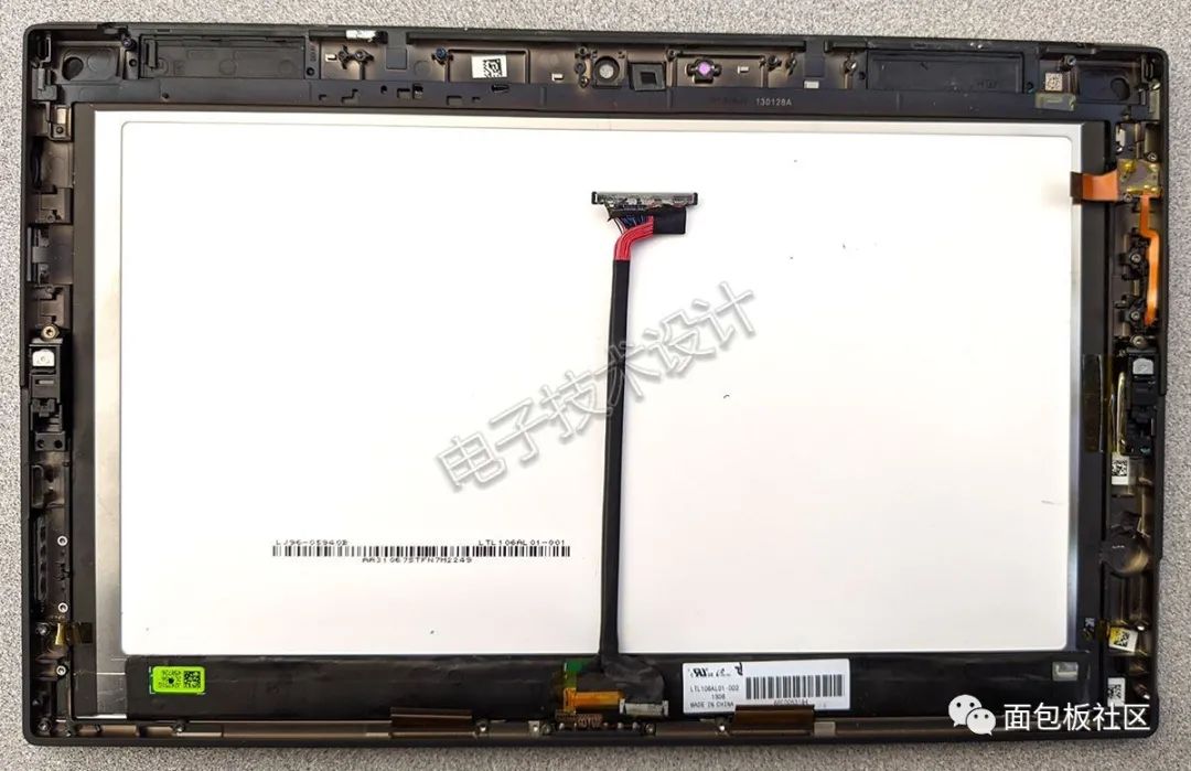
Figure 22: The top side of the motherboard and remaining parts.
What might first strike you as odd is the complete absence of a system fan. Of course, this design is not unique for thin laptops and tablets. Perhaps more noteworthy is the complete lack of any type of passive aluminum heat sink (which is usually quite heavy). However, you might recall, like I did, that this tablet laptop is not based on an x86 CPU system but on a typically more power-efficient Arm architecture system, which has better heat dissipation.
Before we explore the inside of the Faraday cage, let’s flip the PCB over (Figure 23). There is not much to say about this side, just two obvious microphone array ports and two antennas next to them.
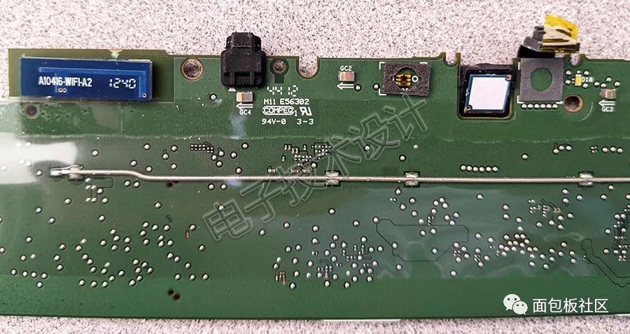
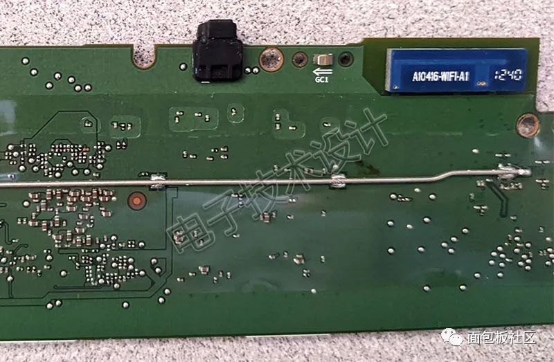
Figure 23: The back of the top motherboard only has two microphone array ports and two antennas.
I suspect one of the antennas is for providing 2.4GHz Wi-Fi communication and Bluetooth, while the other is for the 5GHz spectrum. However, it is also possible that the Bluetooth antenna is embedded in the PCB; what do you think?
Back to the front, first remove the camera module (Figure 24), both of which are 720p resolution.
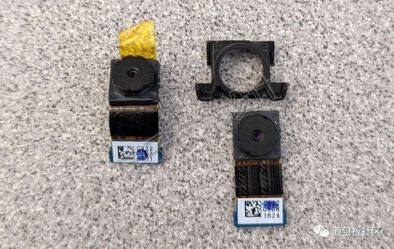
Figure 24: Camera module.
Next, remove the Faraday cage (Figure 25).

Figure 25: The top motherboard after removing the Faraday cage.
Among all the components, a small amount of thermal paste is immediately visible for thermal management. Unsurprisingly, under the thermal paste is the NVIDIA Tegra 3 SoC configured with a 4-plus-1 quad-core Arm Cortex-A9 (Figure 26); next to it is a Winbond 25Q32BV 32Mb SPI serial flash memory, possibly used to store BIOS boot code.
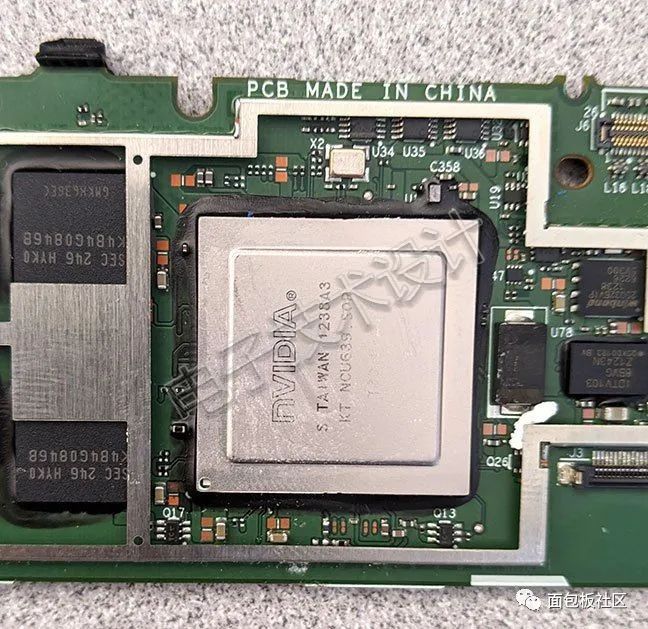
Figure 26: NVIDIA Tegra 3 SoC.
As shown in Figure 27, on one side of the circuit board, you can see four Samsung K4B4G0846B 4Gb DDR3 SDRAM, providing a total of 2GB system memory. Additionally, there is a Marvell Avastar 88W8797 2×2 WLAN/Bluetooth/FM SoC, along with corresponding RF micro-devices RFFM8200 and RFFM8500 Wi-Fi front-end modules.
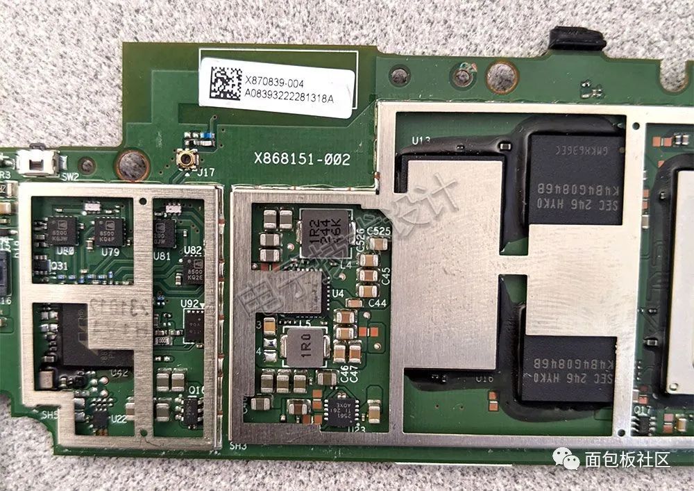
Figure 27: The side of the circuit board contains SDRAM, WLAN/Bluetooth/FM SoC, and Wi-Fi front-end modules.
As shown in Figure 28, on the other side of the circuit board, you can see a Sandisk 32GB flash storage module, a TI TPS65911 power management unit (PMU), a Wolfson 8962E stereo audio codec, and a Cypress Semiconductor CY8C20466A CapSense 8-bit PSoC. Also, note that in the middle of the PCB, there is a strange empty space marked “J14”, indicating a connector.
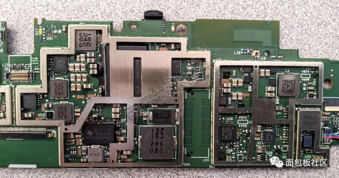
Figure 28: The other side of the circuit board contains flash storage module, power management unit, audio codec, etc.
The Surface RT may no longer be in production, but traces of it can still be seen in Microsoft’s Surface Pro X series. The Surface Pro X series uses a more powerful Arm architecture chip co-developed with Qualcomm, which can not only run native Arm-compiled code but also supports emulation of x86 compiled software in 32-bit (64-bit coming soon). Of course, Apple is also transitioning its entire computer product line from Intel’s x86 architecture to its own Arm architecture SoC, which is a testament to this concept. Reader friends, what are your thoughts on the design of the Surface RT or Surface Pro X products?
Source: EDN Electronic Technology Design