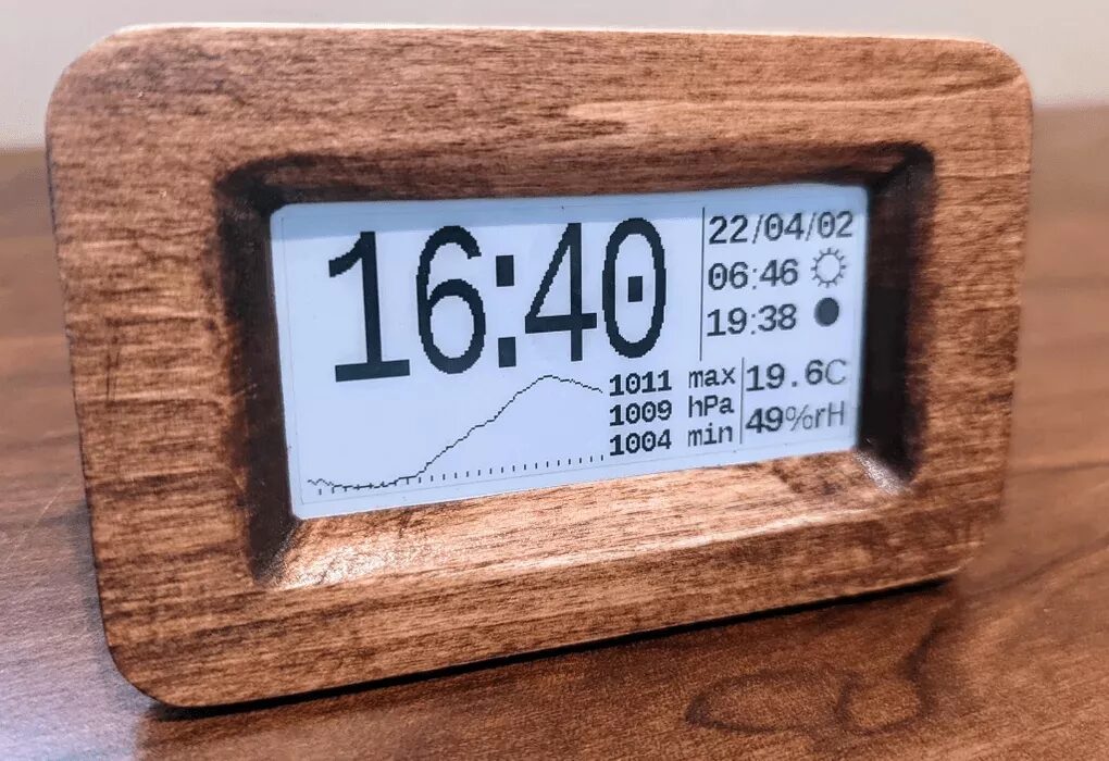
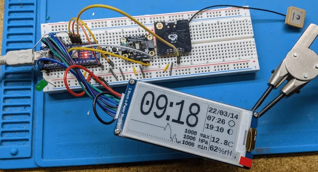
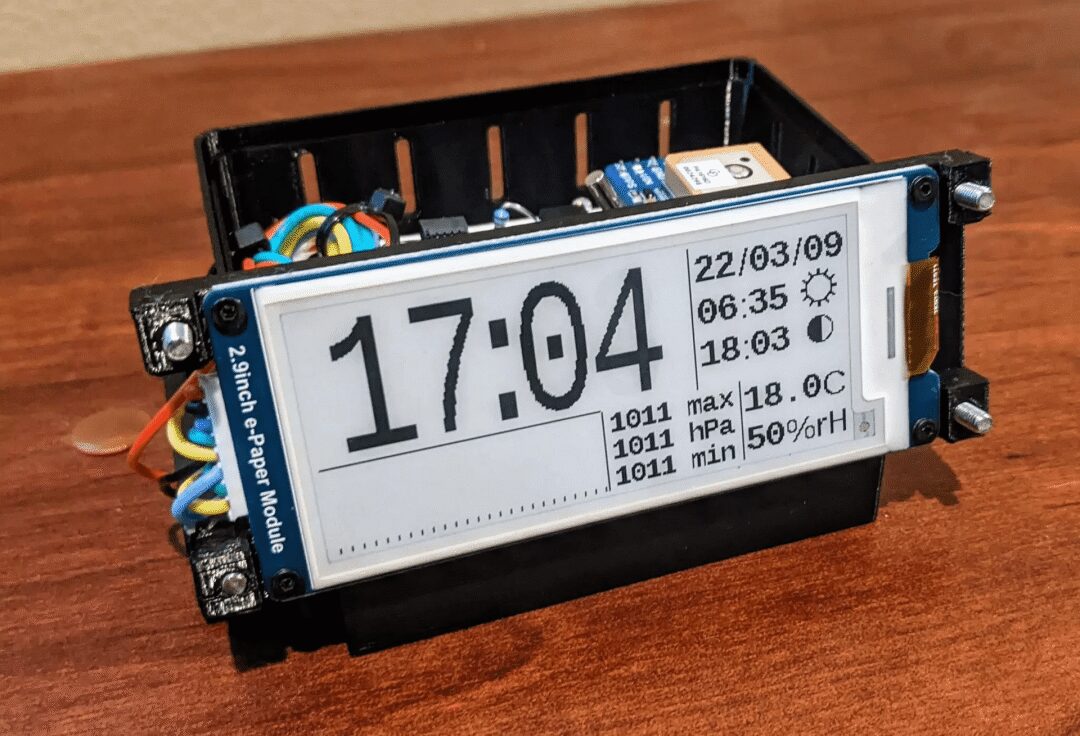
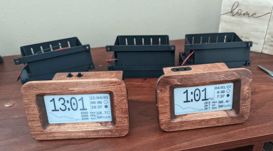
This week, I will introduce you to a beautiful e-paper clock that also functions as a weather station (can automatically set via GPS). It can run for about 6 months on 4 AAA batteries, and to ensure safety and reliability, it does not require any network connection.
Features include:
-
Automatic setting (via GPS)
-
Current temperature.
-
Current humidity.
-
Pressure graph showing the last 25 hours of pressure.
-
Sunrise and sunset times
-
Current moon phase
-
Choose between 12-hour or 24-hour mode.
-
Choose between English and metric units.
This project has two different versions: “Easy” version and “Low Power” version.
The “Easy” version is based on the Arduino Nano. The goal of this version is to minimize cost, the number of parts, and the complexity of making it; the downside is that you need to power the clock with a USB 5V adapter.
The “Low Power” version uses a 32k oscillator to maintain accurate timing with very low power consumption. This oscillator allows the clock to run on batteries.
Step 1: “Easy” Version Parts List
-
Arduino Nano -
Waveshare 2.9 in E-Paper Module -
Adafruit MS8607 Pressure/Humidity/Temperature Sensor -
Any GPS module with 9600 Baud TX -
PCB (can be a prototype board or a copper board for CNC) -
Several push buttons (to change UTC time offset and display preferences) -
Material for making the case (files in .3mf,.scad, and.dxfwill be provided at the end) -
USB charger and charging cable
Step 2: “Low Power” Version
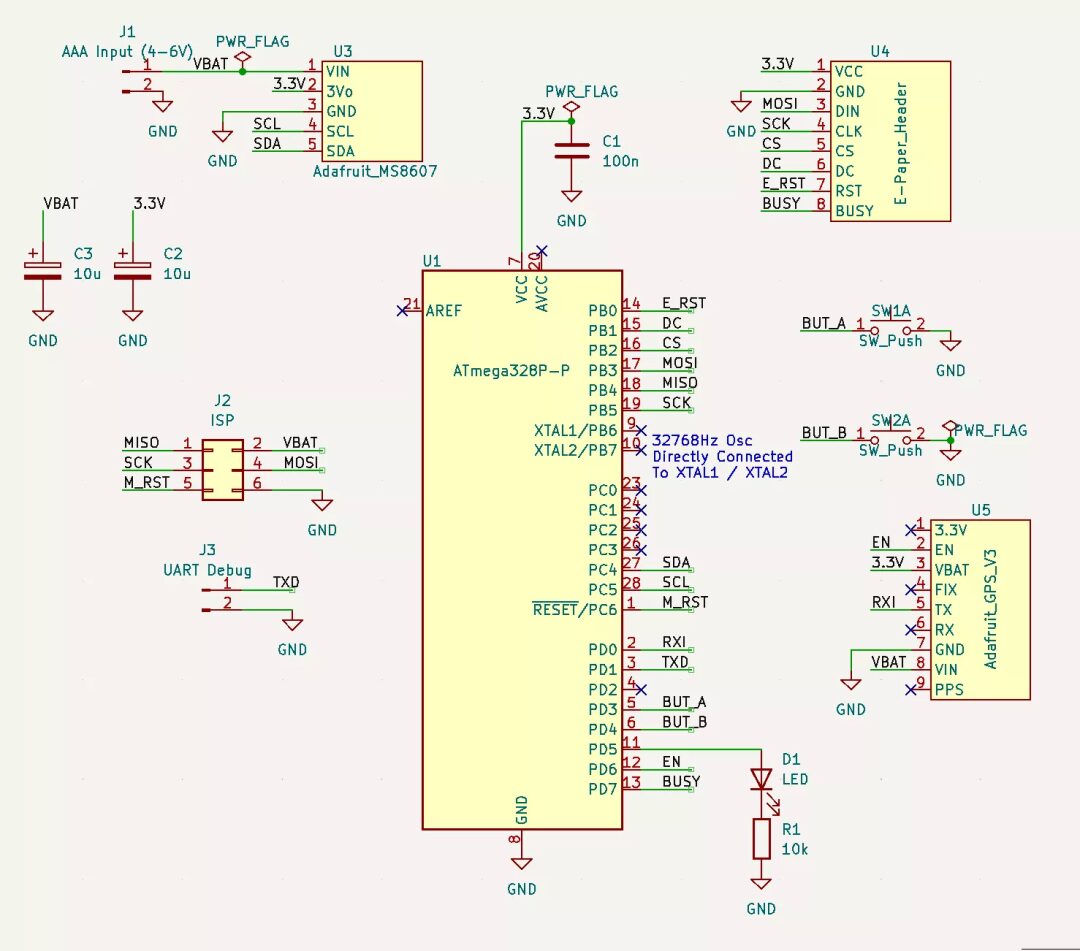
The materials are the same as the easy version:
-
Waveshare 2.9 in E-Paper Module -
Adafruit MS8607 Pressure/Humidity/Temperature Sensor -
PCB -
Several push buttons -
Material for making the case
In addition, you will also need:
-
Atmega328P DIP version (you can also choose the SMD version, but soldering on a 32K crystal is more difficult) -
32768 Hz crystal (this oscillator is key to low power design) -
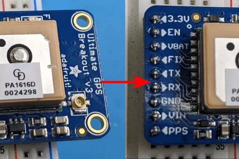
Adafruit GPS module (this module is of higher quality than the one in the “Easy” version, as it can track more satellites (for faster locking), provides an enable pin (for low power), and a port for keeping its memory active (for quick relocking). If all these features are not worth the extra cost for you, you can modify a cheaper module by adding your own enable FET; this will be explained later) -
LED + resistor (the bare Atmega328P cannot tell you if it is working, a blinking light can provide a 1ms/second “heartbeat”, consuming almost no power but providing useful feedback) -
Several 10uF and 100nF capacitors to smooth the power supply voltage -
Batteries (I used 4 AAA batteries, but any battery that can provide 5-7 volts can be used) -
(Optional) A 3×2 pin header for programming the chip via ICSP (if you can remove the Atmega328P for reprogramming, you can skip this connector) -
(Optional) A 1×2 pin header for UART debugging (only needed if the board is unstable)
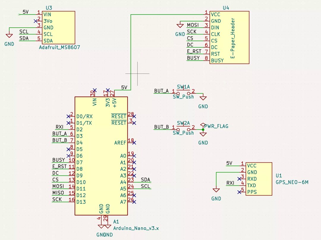
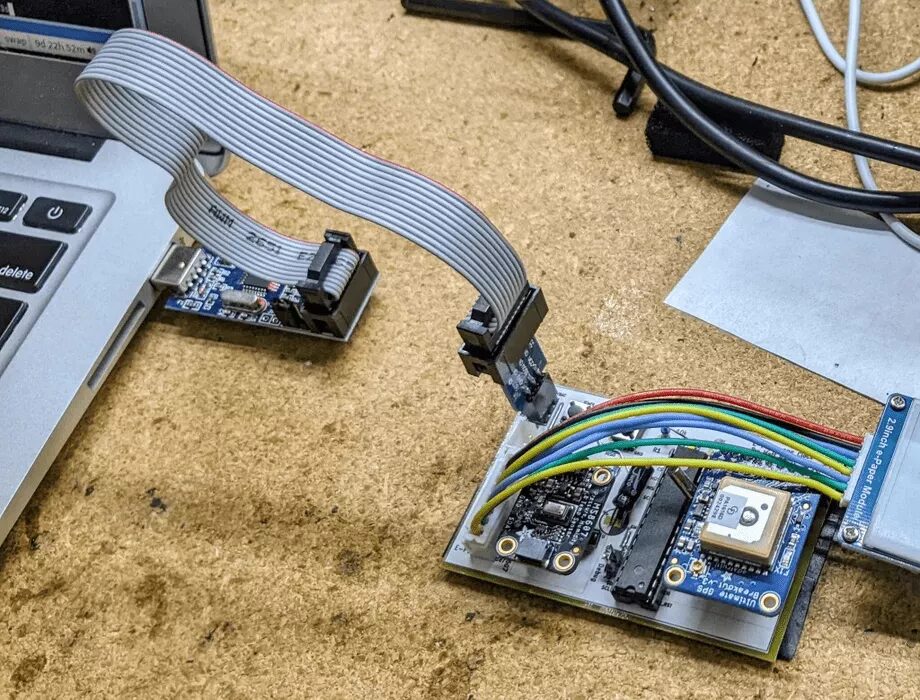
Step 3: Arduino Mini Version
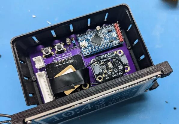
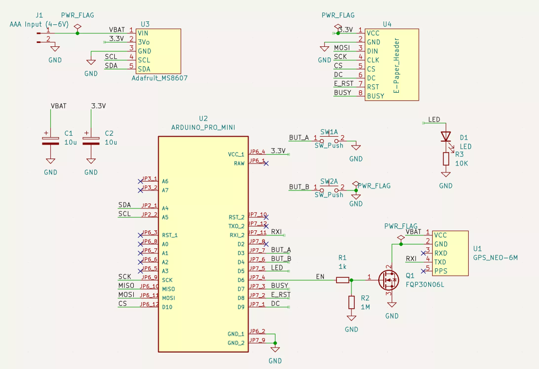
There are two versions mentioned earlier, and this is an additional version. The reason for this extra version is that we are currently in a “parts shortage” where chips like Atmega328P are out of stock for a long time.
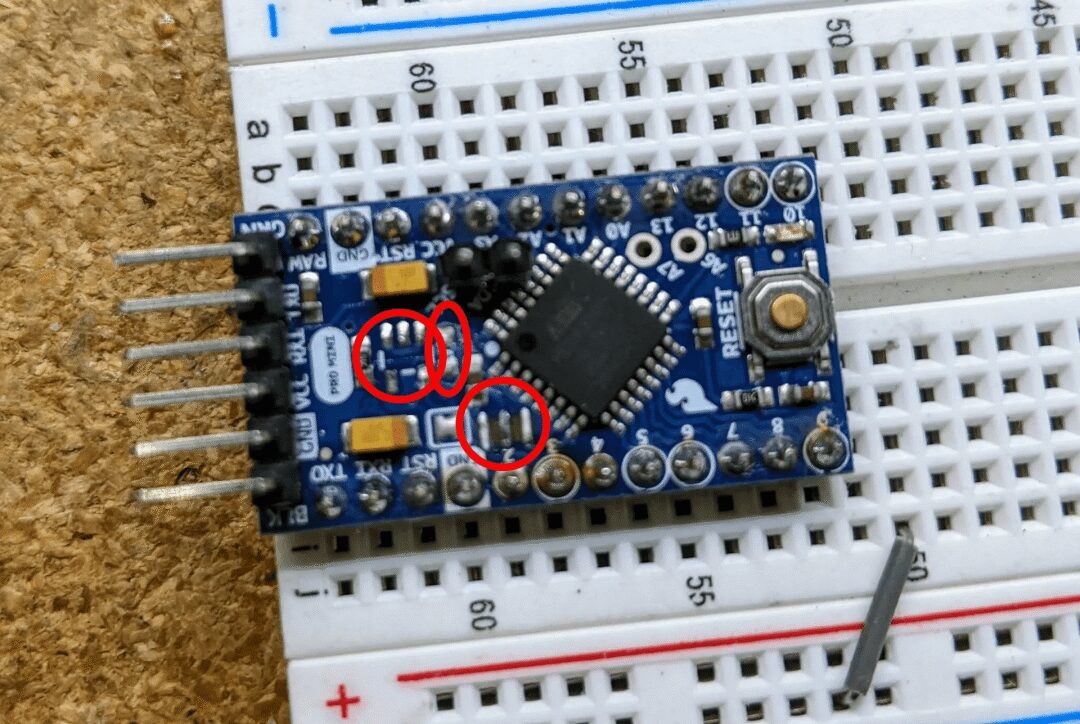
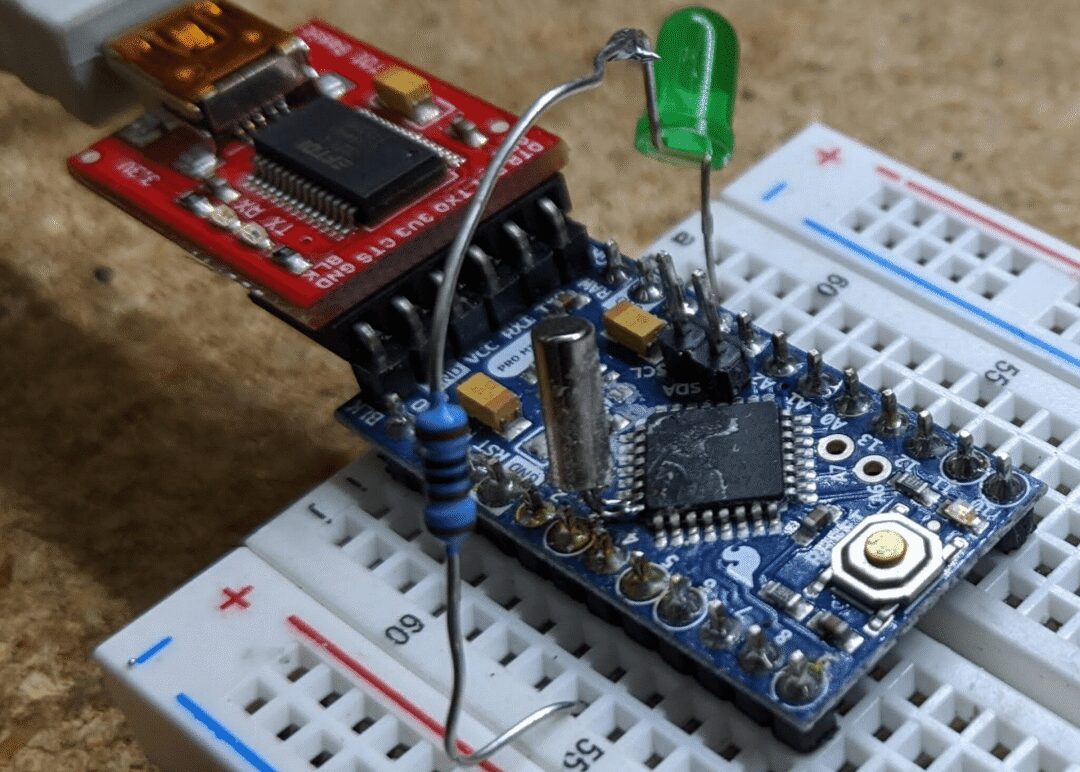
You can run the firmware of the “Easy” version on this version, or if you are confident in your soldering skills, you can solder a 32k crystal onto the microcontroller (as shown in the image above) and use the 32k version firmware (more details in the following section).
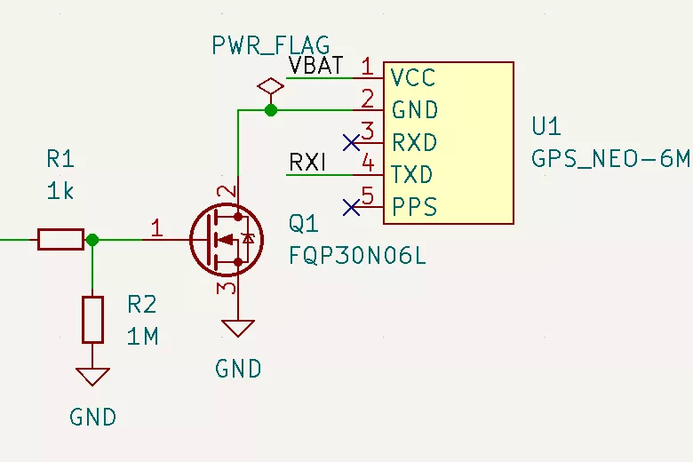
The schematic above is connected using a “cheap GPS” solution, but if you use another (like Adafruit’s) setup to replace the GPS part in the schematic, you can also use other (like Adafruit’s) GPS (as shown in the schematic of the previous step).
Step 4: Cheap GPS (Optional)
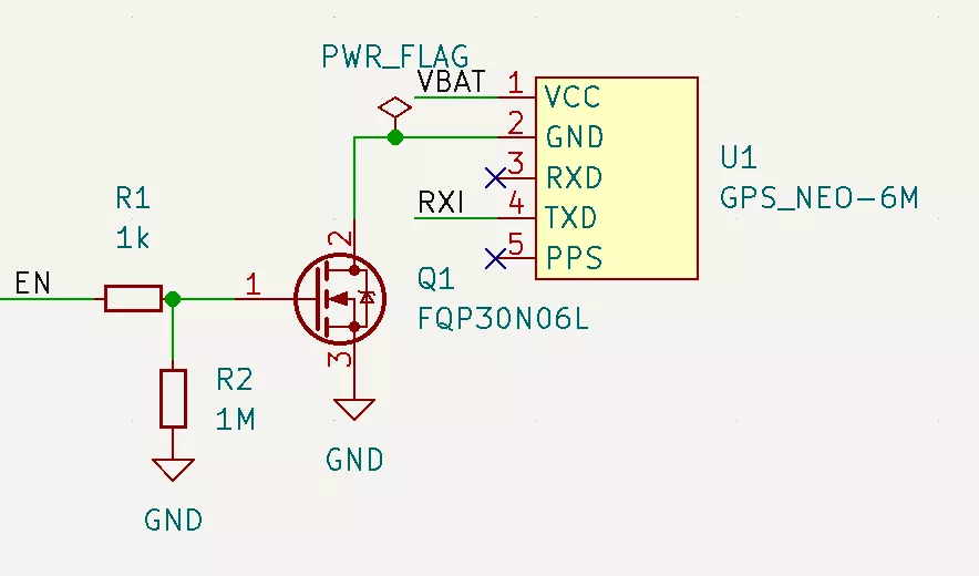
Compared to competitors (12 dollars), Adafruit’s GPS device is expensive (30 dollars). If you think the added features (described in the low-power components section) are not “worth it”, you can throw in any GPS module that can transmit NMEA strings at 9600 baud (most GPS modules can).
But now there is a new problem to solve: Most of these units lack an enable/disable pin, and GPS units typically consume 30-100 mA of power. We can use an N-MOSFET (or similar) to create a disable switch. The schematic above shows the basic idea. We can also try this in falstad[1].
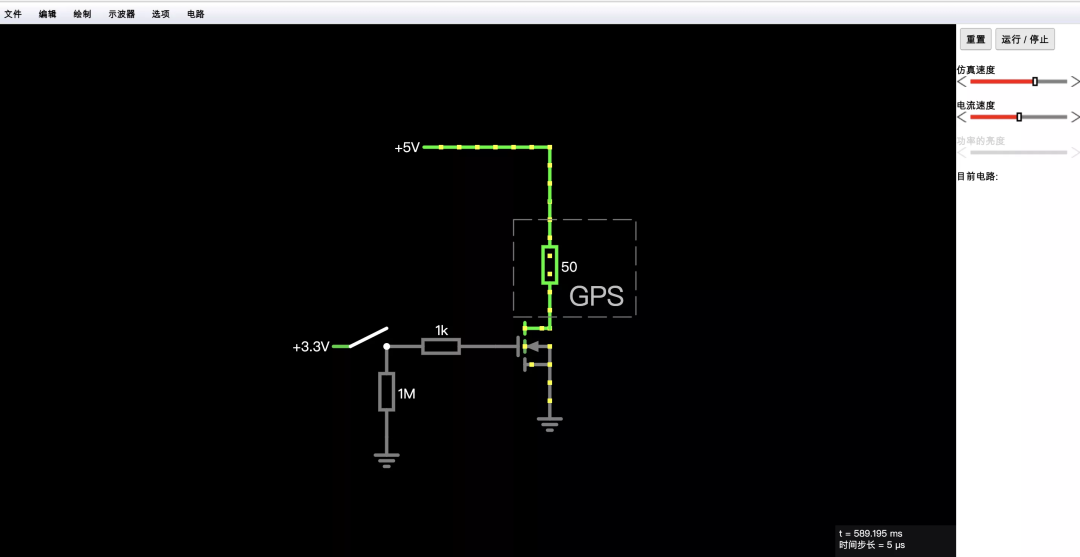
This power switch circuit is a trade-off. If you are interested in more details, see Appendix B.
Step 5: Low Power Hardware Modifications
If you are making the “Easy” version, you do not need to read this section. For the “Low Power” version, these modifications will greatly improve battery life.
To illustrate the issue, we will assume that the power comes from a set of AAA batteries that can provide 1000 milliamp hours. Let’s assume you are using the 32K Adafruit version without making any modifications. Below is an example of a power breakdown.
-
“Sleep/Off” CPU, GPS, MS8607, and E-Paper: measured at 30-70uA (we assume 50uA). -
Screen update: 5 mA, once every 2 seconds: 5 * 2 / 60 = 166 uA -
GPS update: once a day, 50 mA for 10 seconds. 50 * 10 / 86400 = 6 uA -
MS8607 LED: 100 uA -
Adafruit GPS pull-up resistor: 500 uA
Thus, we have an average current consumption of (50 + 166 + 6 + 100 + 500) = 822 uA, which equates to about 50 days of power.
If we remove the MS8607 LED and the GPS pull-up resistor, our power consumption will drop to 222 uA, which is about 187 days of power, greatly increasing usage time.
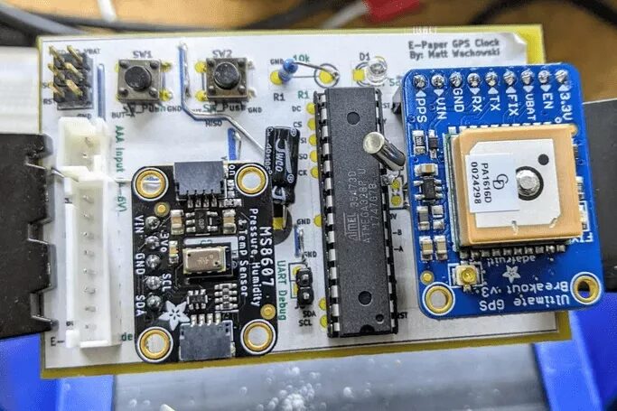
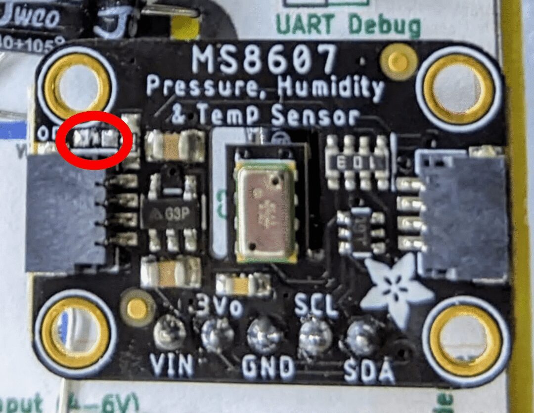
1. First, it is recommended to remove the LED from MS8607 (as shown in the above image).
2. The pull-up resistor on the Adafruit GPS was added by Adafruit’s designers, making the EN pin optional. However, it also has a downside: when you pull it to ground (disabling GPS), about 500uA of current is consumed in the pull-up resistor. Since this design’s enable pin is actively driven, you can remove this resistor (as shown in the above image).
3. Professional mini modifications. Search engines for “Arduino mini low power” for details; basically, you will want to remove the voltage regulator and LED to reduce power usage. We switched to the MS8607 voltage regulator (3.3V, losing 35-55uA at idle) to power the pro mini.
4. In the pro mini photo, I also removed the crystal oscillator to prepare for the 32K crystal chip. Only remove this crystal in the case of the 32K crystal version, and only after reprogramming the fuses on the pro mini, which will be explained later.
Step 6: Firmware
In this step, I have attached the .hex files for both the nano and 32k crystal versions (both versions are suitable for pro mini; if you are unsure which version to use, just use the nano version).
If you want to build/modify the source code yourself, you can visit GitHub: https://github.com/mattwach/epaper_clock
Build Your Own .hex Firmware File (Optional)
Note that this code does not use the Arduino library because the generated code is too large to install on the Atmega328P (and it is my personal preference). It is written in C language, using the Arduino[2] AVR base library as a foundation. If you want to compile the code, you need to install the (free) avr-gcc tool[3], clone the epaper project[4] source code, then navigate to the firmware/[5] directory and enter.
make
If the code builds, you can open the Makefile[6] to see these options.
# This is the Low-power stand alone chip configuration.
CLOCK_MODE ?= USE_32K_CRYSTAL
UART_MODE ?= HARDWARE_UART
F_CPU ?= 8000000

# This is the easy-to-build firmware that is based on an Ardino Nano
#CLOCK_MODE ?= USE_CPU_CRYSTAL
#UART_MODE ?= SOFTWARE_UART
#F_CPU ?= 16000000
If you are building the 32k crystal firmware, the configuration is already correct. If building the nano version, you need to comment out the 32k part, uncomment the nano part, and then run make again.
There is also a special debug mode that dumps log information via hardware UART at 9600 baud. You can ignore it for now, but remember it, as it may be useful later.
# Uncomment to activate debug via the UART TX (9600 baud)
#DEBUG_CFLAG := -DDEBUG
Lastly, you can decide how long the GPS should be activated by changing a few variables. By default, it runs once a day, but if the GPS takes a long time to lock, it will reduce the frequency of operation, thereby reducing battery consumption. Please read src/gps.c[7] for all relevant details.
The files for this section can be downloaded at the end!
Step 7: Upload Firmware Using ICSP
This section is for those uploading code to a standalone Atmega328P chip; if you are uploading to an Arduino Nano, please skip to the next step.
You will need an ISP (or ICSP) programmer. You can make one using a spare Arduino Uno/Nano. You can search for "Arduino ISP Programmer" in search engines. Note that many of these guides assume your true goal is to install a bootloader, but for us, we do not need a bootloader since we will upload the .hex file directly using ICSP.
Power Failure Detection
On my Atmega328P, the power failure detection is set to 3.5V (seems to be an old version), so I used this command to disable power failure detection.
/usr/bin/avrdude -patmega328p -cusbasp -Uefuse:w:0xFF:m
Your setup may differ, depending on your “ISP programmer” (-c option). You may also not need to set this, just in case.
Step 8: Using Avrdude
We can use a free tool called avrdude to upload the hex file it created to your Uno/Nano. We can also download and use avrdude directly from the command line.
-
Run an upload with Arduino IDE while the output log is open (like a blinking demo or another demo), and then copy the command it used. Or -
Read the official avrdude documentation[8] or -
Read online tutorials on using avrdude
Here is the avrdude command I used for the nano version (uploaded via make).
For reference:
/usr/bin/avrdude
  -v
  -patmega328p
  -carduino
  -P/dev/ttyUSB0
  -b57600
  -D
  -Uflash:w:epaper_firmware_using_arduino_nano.hex:i
This is the one I used for the ISP version:
/usr/bin/avrdude
  -v
  -patmega328p
  -cusbasp
  -Uflash:w:epaper_firmware_using_32k_crystal.hex:i
This is using Linux. Mac and Windows work fine too, but options like -P will differ (e.g., on Windows it might be -PCOM1).
Again, the files for this section can be downloaded at the end!
Step 9: 32K Crystal
If you are making the “Easy” version, please skip this step. If you are using the 32k crystal firmware, you need to install the crystal for the firmware to work.
First (!) You also need to configure the ATMega328P’s internal fuses to use the internal 8MHz crystal.
Doing this step first is important because the 32K crystal will replace any existing crystal. If you do not change these fuses, the chip will become unresponsive until you reconnect an 8 or 16MHz oscillator.
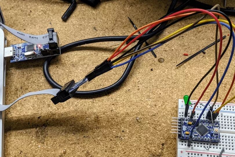
As far as I know, the Arduino pro mini also requires ISP to change the fuses (but I could be wrong). I searched for “Arduino ISP” to get the correct pin mapping to connect the ISP connector to the breadboard (as shown in the image above).
After connecting my ISP programmer, I can use this command to check the current fuse configuration.
$ avrdude -patmega328p -cusbasp
...
avrdude: safemode: Fuses OK (E:FF, H:DE, L:E2)
L:E2 is the setting we want for the internal 8MHz. If your value is different, you can use a command similar to this to update it.
/usr/bin/avrdude -patmega328p -cusbasp -Ulfuse:w:0xE2:m
Then check again.
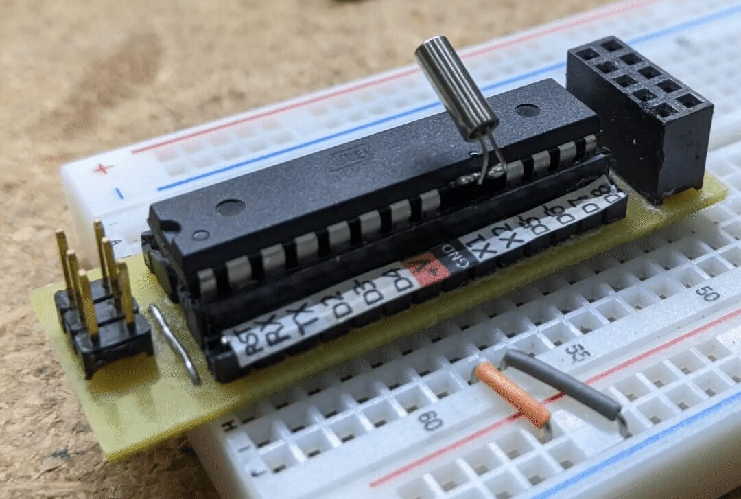
Once the fuse settings are complete, you can solder the crystal. It is recommended to connect the crystal directly to the microcontroller pins to reduce stray capacitance. Too much capacitance can cause the crystal to take longer to start oscillating (or not start at all).
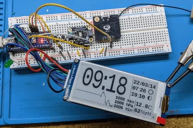
Step 10: (Optional) First Steps
Please refer to the schematic from step 1, step 2, or step 3 of your chosen design.
-
You can verify the current situation on the breadboard by simply connecting an LED/Resistor from D5 to ground and uploading the firmware. If everything is working, the LED will blink briefly once per second; -
Next, you can add the E-Paper display. The data on the display may not be correct, but it should show some data; -
Then, add the PHT module and verify that it works; -
Finally, the GPS module.
If the tests are normal, we can transfer everything to a more “permanent” fixture.
Step 11: PCB Assembly
You can choose to use perf board, CNC cut the board, or send the design to a factory for manufacturing.
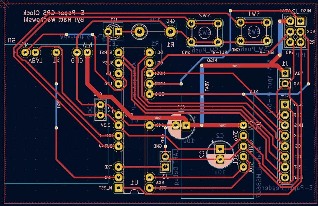
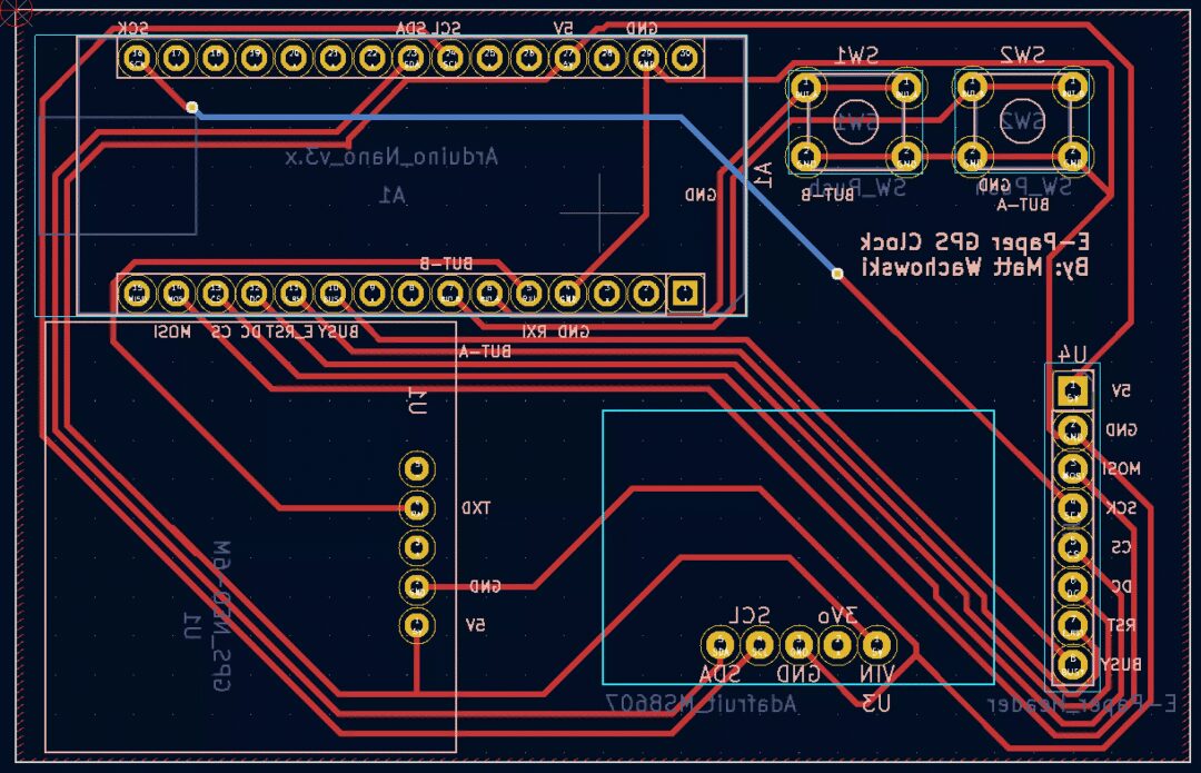
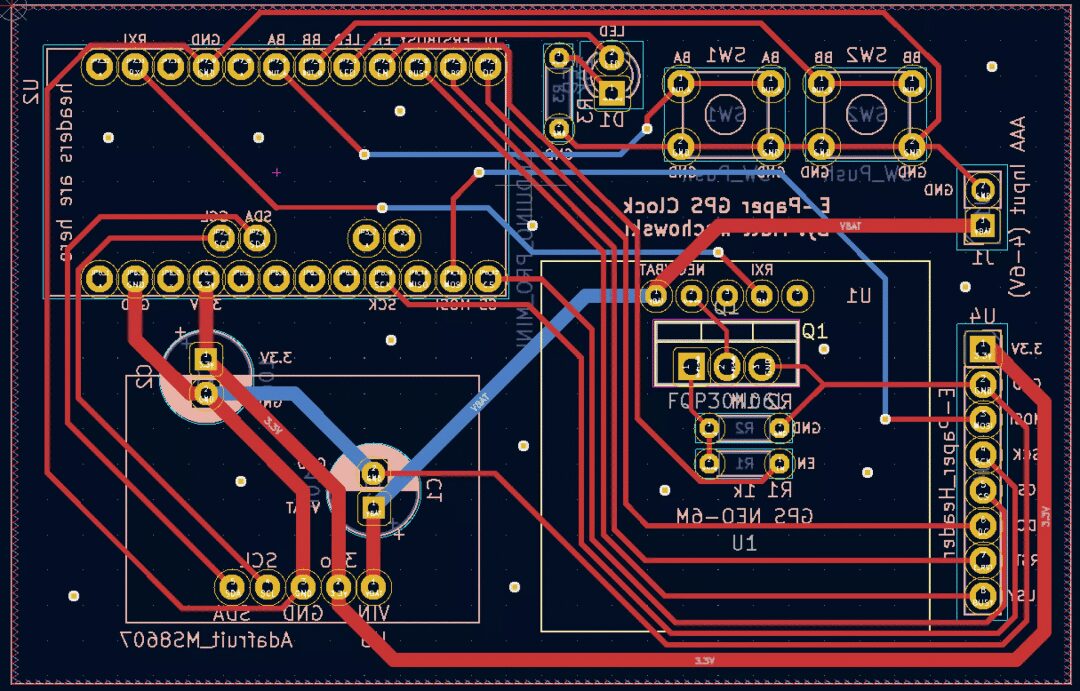
Kicad design files can be found in the schematic/ directory[9]. There are three hardware options available (all shown from the back, as that is how you will wire them manually).
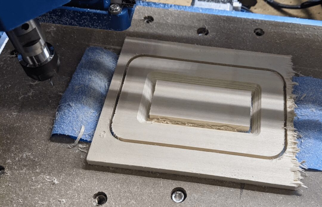
I made the ATMega328P version using my CNC machine. If you haven’t cut PCBs with CNC and are interested, you can try searching for “3018 PCB” in search engines; you will find many videos and articles on this topic.
Gap settings of 0.4 mm, but you can go narrower (probably not wider). I used Flatcam to convert Kicad’s Gerber output to G-code.
Relevant files can be downloaded at the end!
Step 12: Case Design
You can design any type of appearance you want, and everyone is encouraged to be creative!
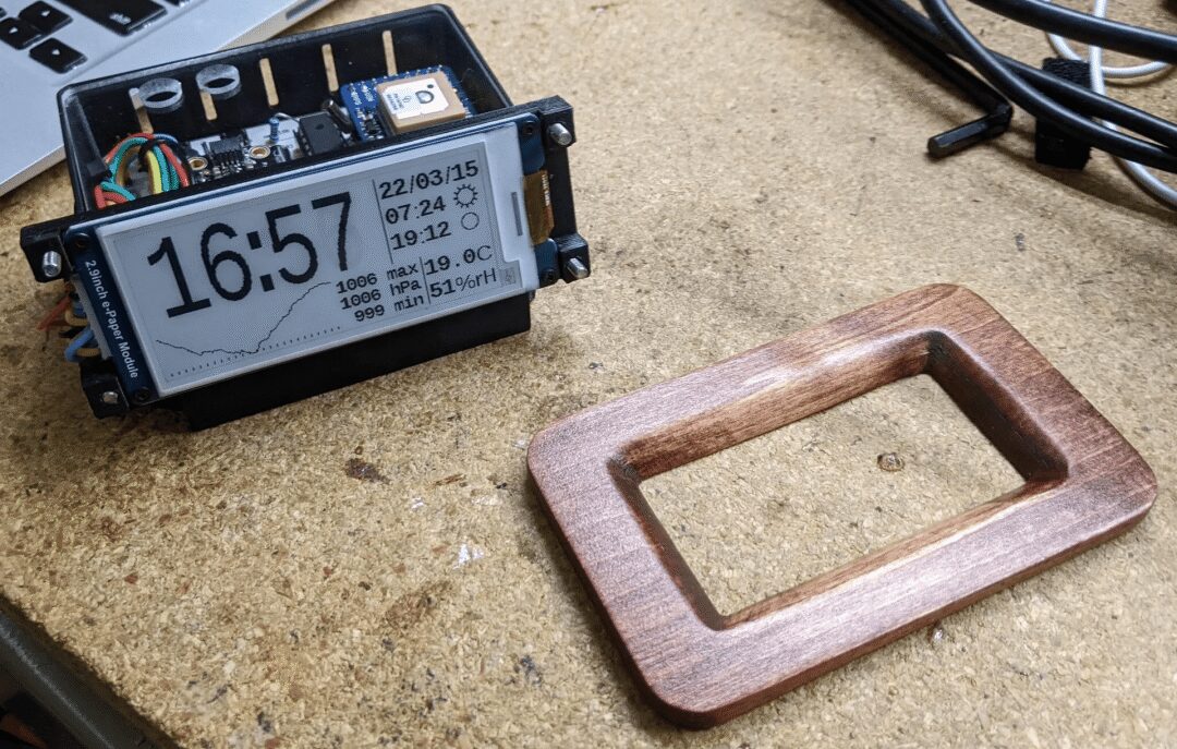
Here I share how I made it (all design files can be downloaded at the end!).
My design used a 3D printed support structure and two CNC parts: a top cover and a front panel. The CNC parts were made of wood because I think it looks nicer than plastic. I pre-designed the whole thing in OpenSCAD.
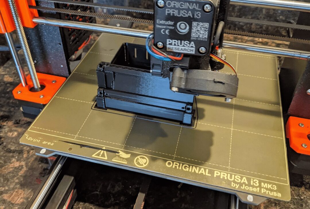
I printed the main structure with a layer height of 0.2 mm. It took just over 5 hours to print on my 3D printer.
I used the “projection”[10] feature of OpenSCAD to create 2D DXF files for the top cover and front panel.
I usually use a free program called “Carbide Create”[11] to create G-code for CNC machines. However, the panel has a 45-degree chamfer, and Carbide Create is too basic a program to handle this well (at least that’s the conclusion I reached after searching their forum on Google). So I tried a different program called “CamBam”[12], which worked very well. (CamBam is not free, but can be used for free 40 times)
Step 13: Appendix A: Clock Drift Correction (Optional)
Your 32k/CPU crystal will not be perfect. When GPS is on, it will correct the drift. However, if the drift is poor or your GPS signal is weak, you can also apply a correction in the firmware. Currently, this requires building the code. At the top of main.c, there are some commented-out definitions.
// Clock drift correction
// If your clock runs too fast or too slow, then you can enable these
//#define CORRECT_CLOCK_DRIFT
// number of seconds that a second should be added or removed
//#define CLOCK_DRIFT_SECONDS_PER_CORRECT 1800
// define this if the clock is too slow, otherwise leave it commented out
//#define CLOCK_DRIFT_TOO_SLOW
You can uncomment the two #define statements above to enable correction.
Simply uncomment CLOCK_DRIFT_TOO_SLOW (if your clock is running slow). If your clock is running too fast, do not uncomment it. The only thing to do is set CLOCK_DRIFT_SECONDS_PER_CORRECT...
Mathematical Method
Wait for about a day and see how much the clock has drifted. For example, you might wait for 23 hours. If you see that the clock has slowed down by 10 seconds at this time, your correction will be:
(3600 * 23) / 10 = 8280 seconds, per correction.
#define CORRECT_CLOCK_DRIFT
#define CLOCK_DRIFT_SECONDS_PER_CORRECT 8280
#define CLOCK_DRIFT_TOO_SLOW
Non-Mathematical Method
Just try a number like 5000, and refine it when you notice the clock is still too fast or too slow. Still too slow? Try 2500. Too fast? Try 10,000. Keep track and refine iteratively to an acceptable value, like you might have played a guessing game at some point.
Step 14: Appendix B: Cheap GPS Power Control (About BS170 N-MOSFET)
To recap the power control circuit described in Step 4 “Cheap GPS”, the power cutoff circuit above is called a “low side switch”. Its advantage is that it is relatively easy to understand and has fewer parts. However, there are some design issues.
-
The ground of the GPS is not connected to GND, but to the MOSFET. This means that the UART signal from the GPS to the microcontroller will have the MOSFET’s voltage drop (Vds) added to it, increasing noise sensitivity and potentially causing errors. -
If the input of your microcontroller is specified to a maximum of 3.3V, you would not want to use this design (the ATMega328P I chose does not have this limitation). -
3.3V (the EN pin above) is not a very strong turn-on voltage for each MOSFET.
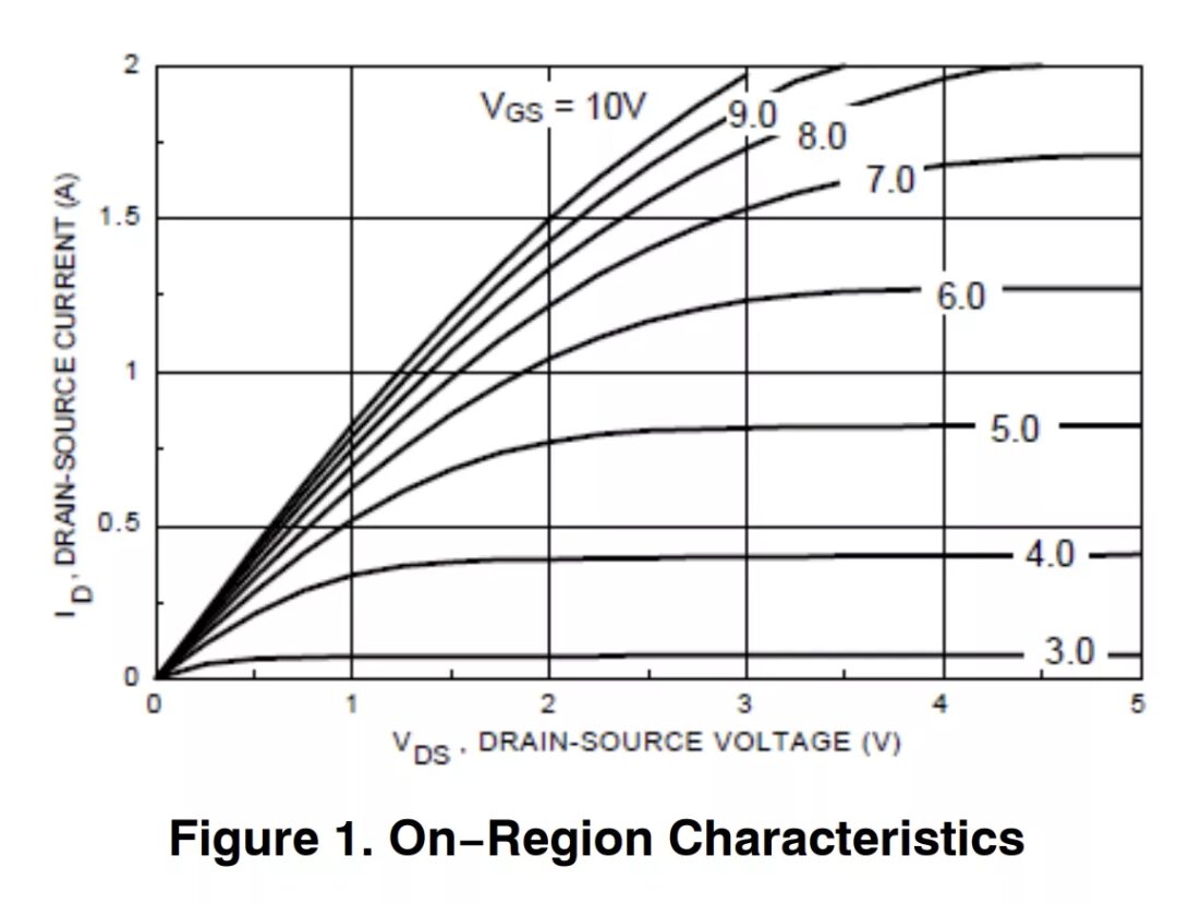
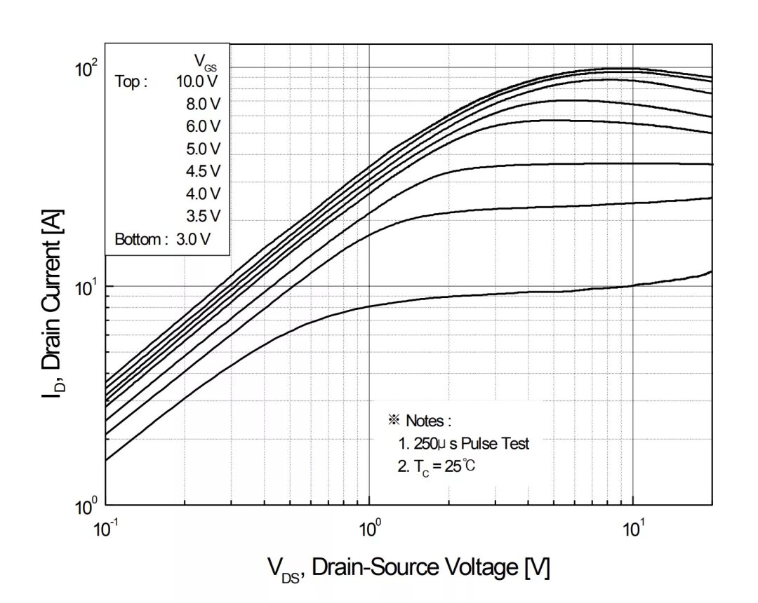
However, UART is a digital signal, and the ground difference is not significant, so maybe it will work anyway? I tried it, and it worked well… at first, but over time I gradually found it to be unreliable. To understand why, we refer to the characteristics curve of the BS170 I initially chose as my N-MOSFET[13].
At 3.3V on the X-axis, we will be sitting between the 3.0V and 4.0V lines on the graph. So, maybe we will get 100mA? Maybe enough?
A multimeter tells me that the GPS consumes 40-60mA, but I think this is an average. Depending on what the GPS is trying to do, it just needs more current than the transistor can allow, causing the GPS ground (MOSFET drain) voltage to rise. This causes both UART errors and lowers the overall voltage of the GPS device, which sometimes still works but sometimes goes into a reset loop.
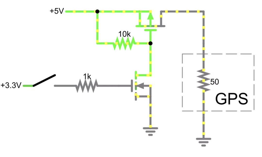
One solution is to use a “high side” power circuit, adding a P-MOSFET to achieve this. See the schematic above. This eliminates the separate ground issue and provides a full 5V (battery) gate voltage fluctuation, which will fully turn on the relevant P-MOSFET.
Here[14] is an example of a high-side design in falstad.
Currently, I have ordered a PCB with low-end wiring, so my secondary solution is to abandon the BS170 and replace it with the FQP30N06L. This higher current MOSFET (maximum 30A!) seems to be seriously overkill, and indeed it is, but its curve looks much better. At 3.3V, there is about 10A of current headroom, improving by 100 times over the BS170, and should now be sufficient; plus, it really has not shown instability in recovery.
References
falstad: http://www.falstad.com/circuit/circuitjs.html?ctz=CQAgjCAMB0l3BWcMBMcUHYMGZIA4UA2ATmIxAUgoqoQFMBaMMAKADMLiUQUAWKwvx5Ds3MNCQwELAEoUMhEIIphuyqlSGSoUCSwBOSoczVCUfHZRYAPJQnJpeIDJAeuQTiwHEACgGUWACMlfHAUPGcwRRQwJ0gWAHd5RWVBATjEo3Ss8FUoFgBzHJQEFJFIOPzDBC5hTWJooSoweFkPZT5NUTqdTSpsaGxe3WkAZ3bPIV4GnuaQNgBDABtRugMPGc6NxVENZHg4Qu2QXePsbEUNFiA
[2]Arduino: https://www.arduino.cc/
[3]avr-gcc tool: https://www.pololu.com/docs/0J61/6.3
[4]epaper project: https://github.com/mattwach/epaper_clock
[5]firmware directory: https://github.com/mattwach/epaper_clock/tree/main/firmware
[6]Makefile: https://github.com/mattwach/epaper_clock/blob/main/src/Makefile
[7]src/gps.c: https://github.com/mattwach/epaper_clock/blob/main/src/gps.c
[8]https://www.nongnu.org/avrdude/: https://www.nongnu.org/avrdude/
[9]schematic/: https://github.com/mattwach/epaper_clock/tree/main/schematic
[10]projection feature: https://en.wikibooks.org/wiki/OpenSCAD_User_Manual/Using_the_2D_Subsystem#3D_to_2D_Projection
[11]Carbide Create: https://carbide3d.com/carbidecreate/
[12]CamBam: http://www.cambam.info/
[13]N-MOSFET characteristics curve: https://www.onsemi.com/pdf/datasheet/mmbf170-d.pdf
[14]High-side design example in falstad: http://www.falstad.com/circuit/circuitjs.html?ctz=CQAgjCAMB0l3BWcMBMcUHYMGZIA4UA2ATmIxAUgoqoQFMBaMMAKADMLiUQUAWKwvx5Ds3MNCQxIKdiEFUwGQnKFgUeELwjjJsGQCcVCpRULHlC+JBYB3OX3DrTCp9bsIzjjR-NQWAJWcvTWJlNQ0qKiFJKCgJFkMMNHATJKp1CJoWAA8QHHIiDQw8AowIXmEQAHEABQBlFgAjOTwNMC480J5ivwBzPOSMgapRSL87Qg9gtOC3YenkxQtbIxTleR4Ha36NlCmN3ArIhM5uPiiu89iweADNQWEo0UfYqJHobFe4hBYAZ3uKldeJchAoQGwAIYAG1+dBYQA
Translation first published: DF Maker Community