
Note:
[1] Please do not switch to FBWA (fixed wing mode other than manual) on the ground; this will unlock the motors when the throttle is pushed (including multirotor motors).
[2] Please do not switch directly from multirotor mode to fixed wing manual mode (MANUAL); this will cause the multirotor motors to stop immediately, which may result in a crash if altitude is insufficient.
[3] When switching back to multirotor, please use QSTABILIZE or QHOVER mode.
New firmware version (V3.8.2) can now switch directly from fixed wing mode back to multirotor QLOITER mode (will glide automatically until airspeed < 5 or Q_TRANSITION_MS time is reached).
[4] For return-to-home, please do not use QRTL mode; use mixed RTL (Q_RTL_MODE=1 to enable mixed RTL), [Mixed RTL settings method]
I am using Ardupilot’s Plane (fixed wing firmware), which is the familiar Mission Planner + Pixhawk, rather than the PX4 native firmware with QGroundControl, and there is no need to mess with Arduino mixed control! The installation method will be viewed from the perspective of multirotor, so no fixed wing operation experience is required; anyone familiar with multirotors can assemble a VTOL by themselves.
First, let’s take a look at the test flight video; the operation method is very simple, just treat the plane as a multirotor.
Video link:
http://v.youku.com/v_show/id_XMTkyNDE4OTc4NA==.html

Steps one and two are the assembly of the carrier, which may have specific instructions for certain brands or specific carriers, so we will skip them and start from step three.

Those who can DIY multirotors should find this easy; basically, it’s just assembling an H-frame and embedding it into the fixed wing’s wings, there are no special techniques, just glue it tightly.
Flight Controller: Pixhawk/Pixhawk2Cube/Pixhack V2 or V3 are all acceptable.
Motors: For 1.4 meters (under 2Kg), it is recommended to use 2808500KV (6S), 750KV (5S), or 900KV (4S).
For 2 meters (under 3Kg), it is recommended to use 3508380KV (6S) or 4108/4110.
ESC: Hobbywing 35A (Mini) or 40A (Standard) or Platinum 30A are all acceptable.
BEC: External 5A 6V (or high voltage 7.4V), depending on the servos.
Note: Whether the BEC can be connected to Mainout as a backup power source depends on the flight controller’s wiring; the original factory can do this, and if it exceeds 7.4V, it is fine (there is protection, it will not be directly introduced), but for third-party manufacturers, it is uncertain; if unsure, do not connect the BEC’s Vcc to mainout.
Image description: All parts of the multirotor
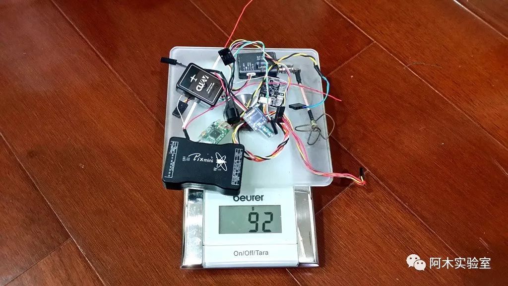
Image description: Multirotor H-frame and reinforcement carbon sheets; I used 10mm for the arms (a bit too thin, 15mm is recommended).
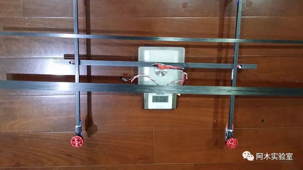
Image description: Grooving the wings to embed a 15mm carbon square tube and reinforcement carbon sheets.
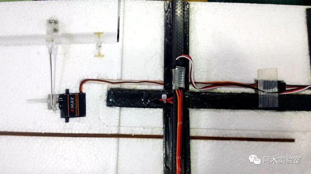
Image description: Embedding the multirotor and completing the reinforcements.
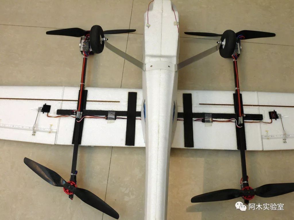
Image description: Installation of the flight controller; this is not a good example because it is not centered…
But this plane has a very small center, and after installing the battery, there is no space left for the flight controller, and the flight controller needs to be frequently removed to check the logs, so it had to be done this way…
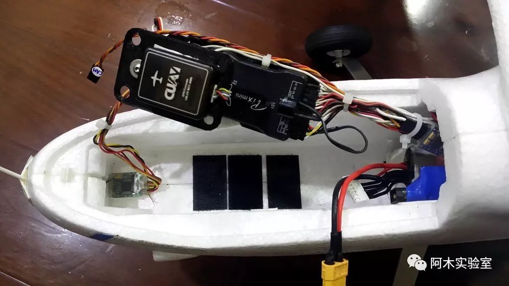
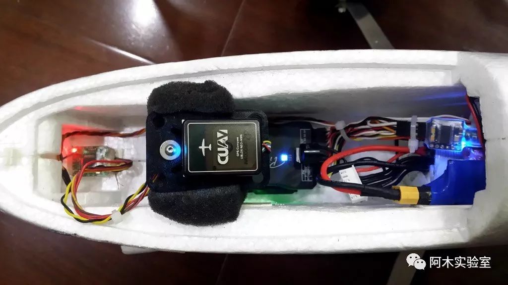
Image description: Fixing the flight controller (using sponge to tighten…), since it is not installed at the center of gravity, you need to set the offset yourself (unit: meters).
INS_POS1_X=0.18
INS_POS1_Z=0.12
INS_POS2_X=0.18
INS_POS2_Z=0.12
INS_POS3_X=0.18 (if there is a third IMU group, such as Pixhawk2 Cube or Pixhack V3)
INS_POS3_Z=0.12 (if there is a third IMU group, such as Pixhawk2 Cube or Pixhack V3)
GPS_POS1_X=0.21
GPS_POS1_Z=0.05
GPS_POS2_X=0.21 (if a second GPS is installed)
GPS_POS2_Z=0.05 (if a second GPS is installed)

(Optional… can also use fixed structure, no need to tilt)
I bought a ready-made one, which is faster; you can find “dual-output servos” on Taobao. Since it is a complete set, it can be easily locked in place, with a pull force of 19 kg, usable at 180 degrees or 270 degrees. In fact, I tested that a 2808 motor + 13-inch propeller only requires about 4 Kg at full throttle, but I couldn’t find a dual-axis servo that can handle 4 Kg, so the wingspan is not recommended to be too small for this reason, as weight is a factor.
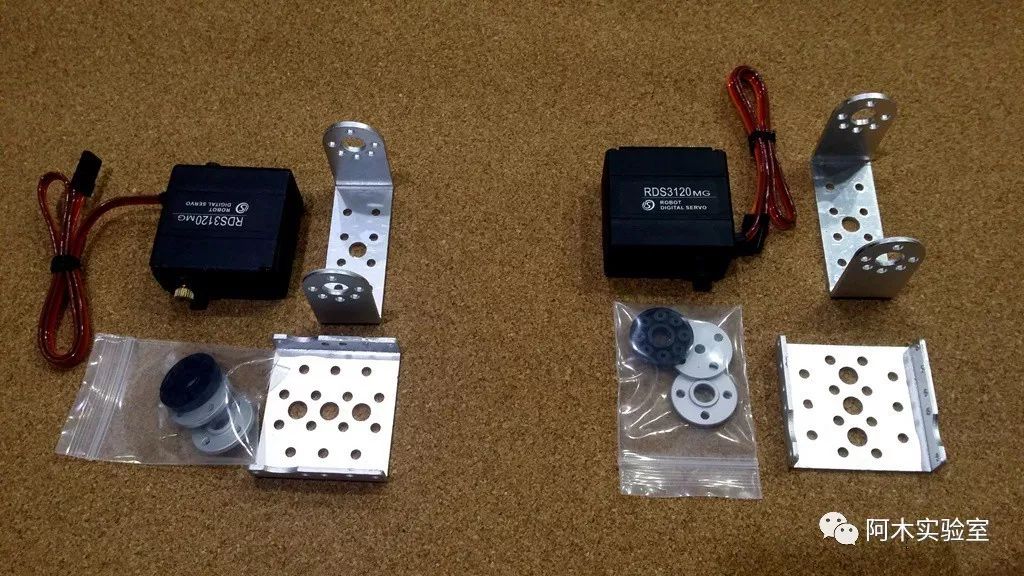
Image description: Weight of two sets of tilt structures
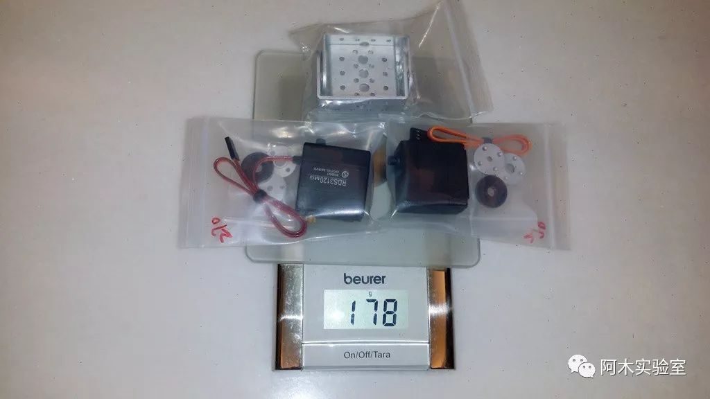
Image description: The original plane’s motor + ESC can be removed, so the weight actually balances out.
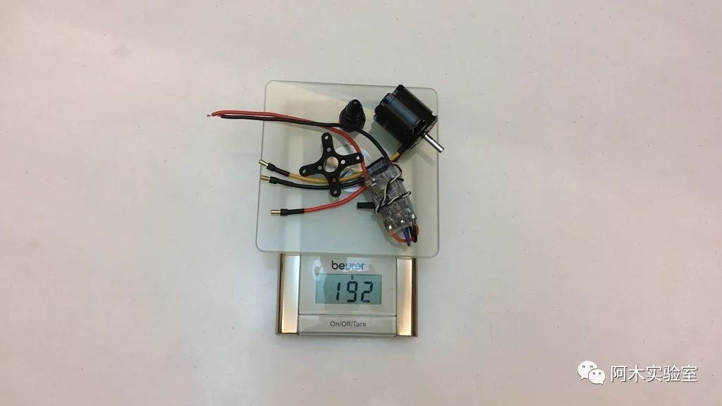
Image description: Dual-output servos fixed in place (0 degrees, multirotor state is 0 degrees).
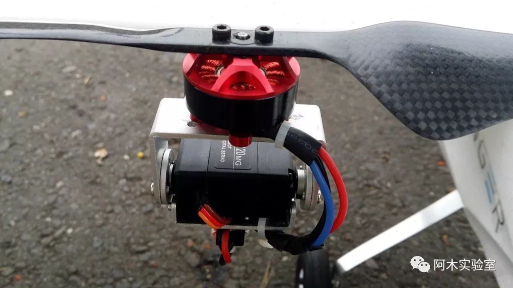
Image description: Dual-output servos fixed in place (90 degrees, plane state is 90 degrees).
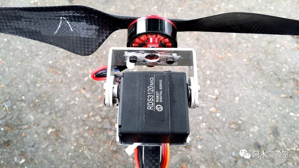
Image description: The two rear motors do not need to tilt (but it can be tilted; it just adds weight, or perhaps change to a pull rod that pulls both front and rear).
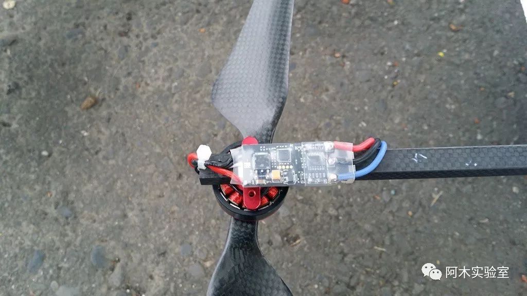
Image description: Dual-output servo parts (bought directly from Taobao, complete set).
Tilt Structure Test Video:
http://v.youku.com/v_show/id_XMTkzMTE3MDg0NA==.html

Wiring Method:
Main out1 (SERVO1): Plane’s aileron (AIL)
Main out2 (SERVO2): Plane’s elevator (ELEV)
Main out3 (SERVO3): Plane’s throttle (THR); if it is a tilt structure, then Mainout3 is idle (not used).
Main out4 (SERVO4): Plane’s rudder (RUD)
Main out5 (SERVO5): Multirotor’s motor 1 (SERVO5_FUNCTION=33)
Main out6 (SERVO6): Multirotor’s motor 2 (SERVO6_FUNCTION=34)
Main out7 (SERVO7): Multirotor’s motor 3 (SERVO7_FUNCTION=35)
Main out8 (SERVO8): Multirotor’s motor 4 (SERVO8_FUNCTION=36, and so on… 33~40 for motors 1~8)
AUX1 (SERVO9): Multirotor’s motor 5; if there is no motor 5, it will be for the tilt servo n (can be assigned by SERVOx_FUNCTION).
AUX2 (SERVO10): Multirotor’s motor 6; if there is no motor 6, it will be for the tilt servo n (can be assigned by SERVOx_FUNCTION).
AUX3 (SERVO11): Multirotor’s motor 7; if there is no motor 7, it will be for the tilt servo n (can be assigned by SERVOx_FUNCTION).
AUX4 (SERVO12): Multirotor’s motor 8; if there is no motor 8, it will be for the tilt servo n (can be assigned by SERVOx_FUNCTION).
AUX5 (SERVO13): If motors 1~8 are all occupied, it will be for the tilt servo n (can be assigned by SERVOx_FUNCTION).
AUX6 (SERVO14): If motors 1~8 are all occupied, it will be for the tilt servo n (can be assigned by SERVOx_FUNCTION).
Note: If using SERVO13 or SERVO14, the PWM count must be changed to 6 (BRD_PWM_COUNT=6), otherwise it will output Relay.
Actually, these wiring are specified by the parameter SERVOx_FUNCTION, so the arrangement can be done according to personal preference; the following tutorial is based on the above arrangement.
Image description: Opening Mission Planner for firmware flashing page.
Note:
* After flashing the firmware, be sure to go to the parameters page and click [Reset to Default Parameters], otherwise the parameter memory values will be unpredictable! Remember!
* Only the first time flashing the VTOL firmware requires resetting; refreshing the version (upgrading) does not require resetting.
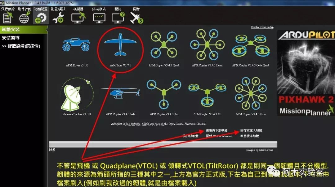
Image description: Enabling VTOL
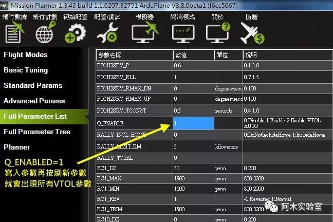
Image description: All Q-prefixed parameters are parameters for the multirotor (actually, removing Q is just like tuning parameters for our multirotor).
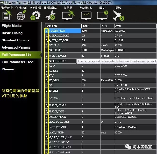
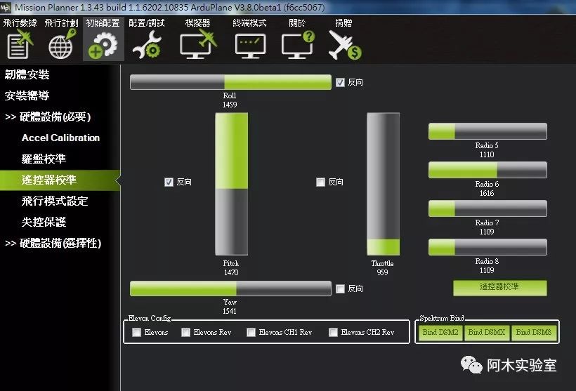
Image description: Calibrating the remote control and confirming the direction of the plane’s servos (the direction may vary between planes, please adjust accordingly).
Note: Before calibrating the remote control, please ensure that the ACC (accelerometer) and compass are calibrated. During ACC calibration, the flight controller can be unplugged and calibrated directly on a flat surface, as the plane is too large (some weighing up to 10Kg or with a wingspan of 5 meters) to calibrate on board; just ensure it is calibrated well before installation, but when installing, it should be kept level with the wings. Usually, FPV-specific machines will have a flight controller seat, and that position is pre-measured by the manufacturer, which is fine.
When powering on the flight controller, there is no need to deliberately keep the plane level, but it should not be too spread out (for example, lying at a 45-degree angle without wheels); keep it still for more than 10 seconds when powered on until the Pixhawk plays the startup completion music before moving the machine.

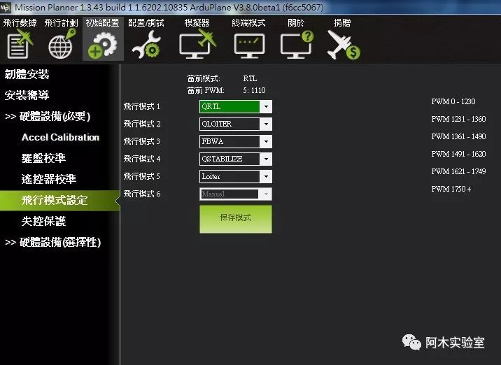
FLTMODE_CH=5 (Mode CH)
The plane’s mode CH is set to CH8, but for those familiar with multirotors, it is CH5, so change it to CH5.
THR_MAX=100 (Maximum throttle for the plane, default is 75%; unless limiting, change it to 100%)
THR_MIN=0 (Minimum throttle for the plane, please change it to 0%)
Q_M_SPIN_MAX=1 (Maximum speed for multirotor motors, including tilt motors, 0.9=90%, 1=100%)
ARMING_RUDDER=2 (Unlocking and locking the plane is different from multirotors, so change it to the same method as multirotors)
Q_M_SPIN_ARM=0.15 (Motor idle speed when the plane is unlocked, which is the idle rotation after unlocking, adjust if too fast or slow)
Q_M_SPIN_MIN=0.2 (Idle speed of the motor when in multirotor mode, which is the idle rotation after unlocking, adjust if too fast or slow)
KFF_RDDRMIX=0.5 (Aileron mixing with rudder, 0=off, higher value means greater effect)
This allows single-handed operation of the plane; using the ailerons will steer while altitude and speed are controlled by Pixhawk (except manual/FBWA).
Q_FRAME_CLASS=1 (Multirotor type, new version of multirotor type, applicable for Beta2 and later ArduPlane-Vx_tiltrotor_V380_beta_0222.px4)
0 Undefined (Error, undefined… if the new version is set to this, all Q-prefixed parameters will disappear)1 Quad2 Hexa3 Octa4 OctaQuad5 Y6
7 Tri (Y3 with a rudder or vector Y3 without a rudder)10 TAILSITTER (tail-sitting)
Q_FRAME_TYPE=1 (Frame type)
0 Cross
1 X or Y6A
2 V
3 H
4 V-Tail
5 A-Tail
10 Y6B
Q_TILT_MASK=5 (Which motors should act as the plane’s power, meaning those motors will tilt)
This is a bits type.
Example (Quad): For a quadcopter, the front two motors will tilt, so the front motor numbers are 1 and 3, which in binary would be: 00000101=5, thus Q_TILT_MASK=5 (this DIY structure is 5)
Example (Quad): For a quadcopter, all motors will tilt, so the motor numbers are 1/2/3/4, which in binary would be: 00001111=15, thus Q_TILT_MASK=15
Example (Y6A): For Y6A, the front four motors will tilt, so the numbers are 1/2/3/5, which in binary would be: 00010111=23, Q_TILT_MASK=23
Example (Y3): For Y3, the front two motors will tilt, so the numbers are 1/2, which in binary would be: 00000011=3, Q_TILT_MASK=3
Q_TILT_TYPE=2 (Enable vector thrust control)
Q_TILT_YAW_ANGLE=10 (Maximum angle of tilt, 10=10 degrees)
Q_TILT_MAX=60 (Less than this angle is multirotor, greater than this angle is plane)
When the tilt is less than 60 degrees, it remains in multirotor mode, and when throttle is applied, the tilt servo will carefully tilt forward, and the front motors will accelerate with the throttle; releasing the throttle will cause the tilt to return and decelerate; this is an acceleration phase, unless the airspeed reaches ARSPD_FBW_MIN=9 (default 9 m/s, about 32 km/h), and the assist speed
Q_ASSIST_SPEED=10, otherwise it will not continue to tilt, and will remain at the set 60 degrees waiting for acceleration to complete; when the speed exceeds the stall speed, it will tilt all the way down (according to the speed of Q_TILT_RATE), and when it tilts down, it becomes a plane, but at this time the multirotor will still maintain balance until Q_TRANSITION_MS=10000 (10 seconds) after which the remaining (non-tilting) multirotor motors will shut down.
If not in manual mode, when in flight and stalling (speed below Q_ASSIST_SPEED=10), the multirotor will immediately engage to maintain balance (to prevent the plane from truly stalling); if the plane rolls in flight (attitude greater than Q_ASSIST_ANGLE=45 degrees), the multirotor will immediately engage to maintain balance (to prevent the plane from truly rolling).
Q_TILT_RATE_DN=15 (Tilting down to fixed wing, speed of tilt servo)
Q_TILT_RATE_UP=50 (Tilting back up to multirotor, speed of tilt servo)
Degrees per second; if set to 30, it means it will tilt down in 3 seconds (3*30=90 degrees); however, it may not necessarily be 3 seconds, as it also needs to wait for airspeed to build; unless switching at a speed, then it will just happen to be 3 seconds.
This speed setting is related to the plane configuration; generally, 20-50 is acceptable; if the transition causes a drop in altitude or a sudden rise, adjust accordingly; this will relate to Q_TILT_MAX; sometimes Q_TILT_MAX also needs to be changed simultaneously; one is the angle and the other is the speed; they need to be matched, and only testing can determine this; if problems are found during testing (sudden drops or rises), immediately switch back to multirotor and readjust; it’s fine!
SERVO9_FUNCTION=75 (=AUX1, vector control – left servo)
SERVO9_MAX=2000 (Maximum angle pwm for the servo, based on actual measurement)
SERVO9_MIN=1000 (Minimum angle pwm for the servo, based on actual measurement)
SERVO9_REV=0 (0=forward, 1=reverse)
SERVO10_FUNCTION=76 (=AUX2, vector control – right servo)
SERVO10_MAX=2000 (Maximum angle pwm for the servo, based on actual measurement)
SERVO10_MIN=1000 (Minimum angle pwm for the servo, based on actual measurement)
SERVO10_REV=1 (0=forward, 1=reverse)
Note: The following restrictions do not include manual mode, which is unrestricted (aerial acrobatics).
LIM_PITCH_MAX=3000 (Limit the maximum angle of ascent for the plane, positive value)
LIM_PITCH_MIN=-3000 (Limit the maximum angle of descent for the plane, negative value)
LIM_ROLL_CD=4000 (Limit the maximum roll angle for the plane, positive value)
The above three units are Centi-degrees; for example, 3000 equals 30 degrees.
Q_ASSIST_ANGLE=45 (When the plane tilts beyond this angle, the multirotor will automatically engage to balance)
The unit is degrees, 45=45 degrees.
Q_ANGLE_MAX=3000 (Limit the tilt angle of the multirotor itself, which is for the multirotor, not the plane)
The unit is Centi-degrees; for example, 3000 equals 30 degrees.
ARSPD_FBW_MAX=25 (Maximum flight speed in plane mode, no restrictions in manual mode)
ARSPD_FBW_MIN=11 (Stall speed in plane mode, no restrictions in manual mode)
The above two units are in meters/second; for example, 10 is about 36 km/h; automatic mode will automatically maintain within this range.
Q_ASSIST_SPEED=12 (When the plane’s speed is below this speed, the multirotor will automatically engage to balance)
The unit is in meters/second; for example, 10 is about 36 km/h.
Q_TRANSITION_MS=6000 (After transitioning to a plane, the multirotor will shut down the balance power after a few microseconds, meaning the non-tilting motors will stop running) unit is in microseconds, for example, 10000ms=10 seconds
Q_VFWD_GAIN=0 (Using tilt motors to accelerate or resist strong winds in multirotor QLoiter mode)
RUDD_DT_GAIN=20 (Dual-motor differential control sensitivity, 0=off, 1~100%), the larger the value, the greater the control force, applicable for all fixed wing modes.
Q_WVANE_GAIN=0 (Active wind sensitivity), the vector type has very good control capability, so active wind can be turned off (default is on, for 4+1 use). TRIM_ARSPD_CM=1600(Default speed for automatic and cruise modes), unit is centimeter/second, 1600 cm = 16 m/s.
Transition Tips 
Q: Transition is slow and jerky?A: Incorrect parameter settings causing Q_TILT_MAX=60 (tilt angle) <– usually this is set too low. Q_TILT_RATE_DN=15 (tilt speed) Q_TRAN_PIT_MAX=6 (maximum allowable degrees of ascent during tilt, 5=5 degrees) Q_WVANE_GAIN=0 (turn off active wind function, as vector models perform well and do not need this assistance) Q_WVANE_MINROLL=2 (increase compensation for crosswinds during transition)
Q: How to transition?A: When the switch is set to FBWA or FBWB, it is already flying in fixed wing mode; just push the throttle, the more throttle pushed, the faster it flies forward; this process is very safe, even if the throttle is pulled all the way back, it will stop at a fixed height; pushing the throttle will accelerate until the airspeed is reached, at which point it will fully tilt down and shut down the multirotor power.

If the old version of Mission Planner does not recognize these modes, enter FLTMODE*=n (as below)
0 Manual (plane manual mode)
1 CIRCLE (plane circling mode, no fixed point, will drift with the wind)
2 STABILIZE (plane self-stability mode, replaced by FWBA, please avoid using)
3 TRAINING (plane training mode)
4 ACRO (plane ACRO mode, similar to manual but can set semi-manual)
5 FBWA (plane linear flight mode, similar to self-stability mode but more stable, no altitude hold)
6 FBWB (plane linear flight mode, similar to self-stability mode but more stable, with altitude hold)
7 CRUISE (plane constant speed cruise mode)
8 AUTOTUNE (plane auto-tuning mode)
10 Auto (plane auto mode)
11 RTL (plane return-to-home mode)
12 Loiter (plane loiter mode, altitude + fixed-point circling)
14 AVOID_ADSB (plane ADSB detection mode, requires ADSB receiver)
15 Guided (plane guided mode)
17 QSTABILIZE (multirotor self-stability mode)
18 QHOVER (multirotor altitude hold mode)
19 QLOITER (multirotor loiter mode)
20 QLAND (multirotor auto descent mode)
21 QRTL (multirotor return-to-home mode)
The transition between the plane and multirotor (tilt) occurs automatically after switching modes; for example, switching from multirotor QSTABILIZE to FBWA will automatically tilt to become a plane, and switching from plane back to multirotor will automatically tilt back.
However, two points need special attention:
1. Switching from multirotor to manual mode (Manual), the multirotor auxiliary motors will immediately stop, which may result in a crash if altitude is insufficient or if the operator lacks manual flying experience. This is used for multirotor failure recovery; the operator must have manual flying experience.
Generally, switch to FBWA first without issue, then switch to manual mode; do not switch directly to manual mode.
2. Switching from the plane back to multirotor mode, only QSTABILIZE and QHOVER modes will tilt back; if switched directly to QLOITER, it will not tilt back, as high-speed fixed-point abrupt stop will separate the wings, which is prohibited.
Note: The new version (V3.8.2, only available in group firmware, not in the official version) can now switch directly from fixed wing mode to multirotor loiter mode (QLoiter), which will automatically glide and decelerate until airspeed <5 (m/s) or Q_TRANSITION_MS=5000 (default 5000=5 seconds) time is reached.

Note: Mixed control has been canceled and replaced with a new method; please directly refer tohttp://t.cn/REVXDMy (77~80), the following is for old versions only.
Actually, any plane model can be understood as a few servos moving together (mixed control); they are just the interconnection of channels! This can be easily solved in Pixhawk, without needing the remote control to intervene…
Taking V-tail as an example:
It is just a mixing control between elevator and direction (channels 2 and 4).
Steps are as follows:
1.VTAIL_OUTPUT=1, KFF_RDDRMIX=0.5 (temporarily set mixing to 0.5, RC1,2,4_REV temporarily set to forward=1)
2. Raise the plane (FBWA mode); if the two V-tails move in different directions, increase VTAIL_OUTPUT by 1 until both move in the same direction.
3. When raising the nose, the control surfaces should all move up (when raising the nose, they should actually move down for correction), indicating that RC2 is wrong and needs to be reversed (RC2_REV=-1).
4. When tilting right, the control surfaces should tilt right (when tilting right, they should actually tilt left for correction), indicating that RC4 is wrong and needs to be reversed (RC4_REV=-1).
5. Finally, confirm the correct direction of the remote control CH2 and CH4 in manual mode; if the operation direction is reversed, reverse the remote control channel.
The flying wing operates on the same principle, but it is just a mixing control between ailerons and elevator (channels 1 and 2).
1.ELEVON_OUTPUT=1, ELEVON_MIXING=0, RC1,2_REV temporarily set to forward=1
2. Tilt the plane right (FBWA mode); if both ailerons move to the same side, increase ELEVON_OUTPUT by 1 until they move in opposite directions.
3. Tilt the plane right (FBWA mode); if the left aileron moves down and the right aileron moves up, it indicates that RC1 is wrong and needs to be reversed (RC1_REV=-1).
4. Raise the plane (FBWA mode); if both elevator surfaces move up (when raising the nose, they should actually move down for correction), it indicates that RC2 is wrong and needs to be reversed (RC2_REV=-1).
5. Finally, confirm the correct direction of the remote control CH1 and CH2 in manual mode; if the operation direction is reversed, reverse the remote control channel.
Note: VTAIL_OUTPUT and ELEVON_OUTPUT will only have 4 combinations (0=off, 1~4); one of these 4 combinations will be correct, if you don’t know how to set it, just try setting it randomly; one of them will be correct, as there are only 4.
What if the mixing ratio is insufficient?
MIXING_GAIN is preset to 0.5, meaning the maximum ratio of the mixed servo is 50% (0=no, 0.5=50%, 1=100%, etc.); if changed to 1, both servos will output to full travel, which can be adjusted according to personal preference.
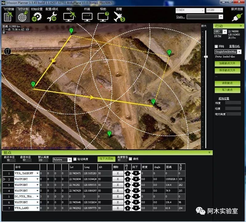
Auto Route Testing.
Shot on a mobile phone, the route range has been set very small, and the height is only 30 meters, but it is still not very clear…
Route Commands:
VTOL_TAKEOFF= Vertically take off to a specified height in multirotor mode, then automatically switch to fixed wing for a short flight.
WAYPOINT= Waypoint
DO_VTOL_TRANSITION=3 (automatically switch to multirotor mode)
DO_VTOL_TRANSITION=4 (automatically switch to fixed wing mode)
VTOL_LAND= Land in multirotor mode; if the previous waypoint was in fixed wing mode, it will automatically switch to multirotor mode.
Test Video:
http://v.youku.com/v_show/id_XMTk4MTU4NzI3Ng==.html