EtherCAT is a high-performance industrial Ethernet technology proposed by BECKHOFF[1]. It uses standard Ethernet data frames and a physical layer that complies with the Ethernet standard IEEE 802.3, featuring high data transmission speed, good real-time performance, flexible topology, and low implementation costs, gradually becoming a hot topic in industrial Ethernet technology research[2].
Currently, EtherCAT technology has become part of the international standard IEC61158 and is widely used in industries such as synchronous control, motion control, and material processing control[3,4]. This paper studies common EtherCAT network configuration schemes, analyzes their shortcomings, proposes an EtherCAT network configuration scheme based on the Slave Information Interface (SII), implements the scheme, and finally verifies its feasibility through experiments.
Most commonly used EtherCAT network configuration schemes are based on eXtensible Markup Language (XML). In this scheme, the EtherCAT configuration tool generates an XML formatted EtherCAT Network Information (ENI) file based on the EtherCAT Slave Information (ESI) file provided by the slave and the network topology. The ENI file describes the network topology as well as the initialization and configuration commands for the slave devices. The master obtains the ENI file and configures the EtherCAT network according to its network configuration information.
This scheme has good universality and scalability, but it also has many shortcomings. On one hand, this configuration scheme requires additional configuration software for assistance, increasing the workload of research and development. At the same time, since the ENI file is generated based on the ESI file, whenever a new module appears, a new ESI file must be added to the library file of the EtherCAT configuration software, making the entire configuration operation relatively complex. Reference [5] designs a simple EtherCAT master that can simplify the configuration process, but it still requires assistance from a host computer.
On the other hand, parsing XML formatted files is relatively complex. The XML format is a text format established by the W3C organization for web data storage and exchange, and its parsing complexity is high, especially in embedded master systems with limited system resources, where the parsing pressure of XML will face even more severe challenges. Reference [6] proposes a fast XML parsing scheme, but it has high memory requirements and cannot completely solve the above problems.
1 Configuration Scheme Based on SII
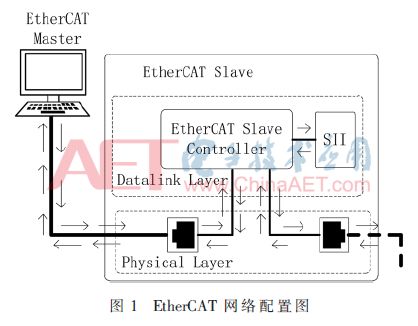
To solve the problems existing in traditional schemes, this paper proposes and designs an EtherCAT configuration scheme based on SII. SII is the Slave Information Interface, which specifies the storage format of slave information in EEPROM, allowing the master to configure the slave based on the information in SII. The configuration scheme is shown in Figure 1. At the start of the configuration, the master scans the slaves, obtains the topology of the slaves, sequentially reads the device information of all slaves, and then generates configuration commands to complete the configuration operation of the EtherCAT network and all slaves. Compared with traditional schemes, in this scheme, the master obtains the topology of the slaves and generates configuration information without the need for specialized configuration tool software, reducing the development cost of the configuration scheme; the master directly obtains slave information from SII without the need for XML, saving the time for XML parsing and greatly improving configuration efficiency.
The configuration scheme includes three operational steps: (1) Scan the slaves and calculate the topology structure of the connected slaves based on the response information obtained; (2) Read the slave information sequentially according to the topology structure of the slaves; (3) Generate configuration information and configure the slaves.
1.1 Calculate Slave Topology Structure
In the currently commonly used EtherCAT network configuration schemes, the topology structure of the slaves is generated and issued to the slaves by the configuration tool software. However, in the SII-based configuration scheme, since there is no involvement of configuration tool software, the master uses a recursive algorithm to calculate the topology structure of the slaves.
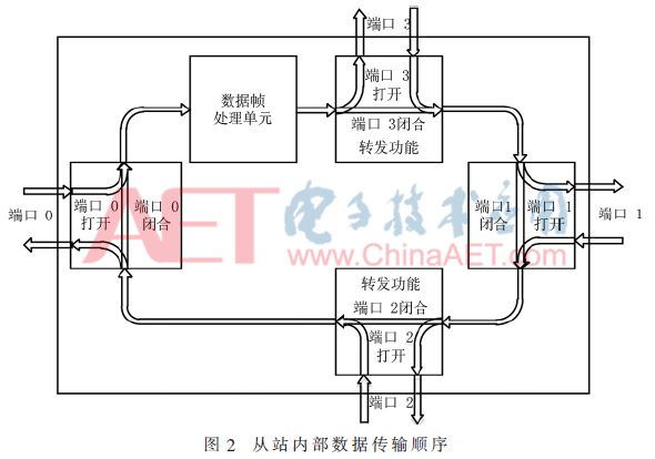
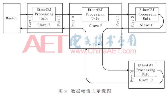
To help readers better understand the method for calculating the topology structure of the slaves, we will first briefly introduce how EtherCAT data frames are transmitted among the slaves. The structure of EtherCAT slaves is shown in Figure 2, where a slave supports up to four ports, and the slave will automatically open or close ports based on whether a connection exists. If a connection exists, the port is opened; otherwise, it is closed. If the port is open, the data frame flowing into that port is sent to other slaves, and after processing by other slaves, it returns to that port; if the port is closed, the data frame will flow directly to the next port of the slave. Port 0 is the input port for slave data, and once the slave connects to the network, port 0 must be in the open state; the other three ports may be closed. Therefore, the order of data frame transmission within the slave is port 0, data frame processing unit, port 3, port 1, port 2, and finally leaves the slave via port 0. Figure 3 introduces the process of data frame transmission in the network.
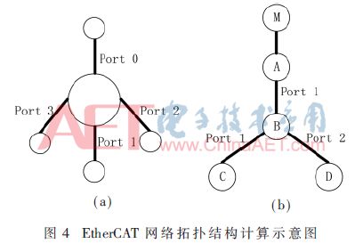
Based on the above description, the EtherCAT slave can be abstracted as a node on a ternary tree. As shown in Figure 4(a), Port 0 serves as the input port of the slave node, while Ports 3, 1, and 2 serve as output ports, with the tree traversal order being Ports 3, 1, and 2. The network topology structure in Figure 3 can be abstracted as a ternary tree shown in Figure 4(b). Therefore, calculating the topology structure of the EtherCAT network can be abstracted as a depth-first traversal of the ternary tree[7]. Because the number of nodes in industrial control networks is relatively small, a recursive algorithm can be used to implement this, so this paper adopts a recursive algorithm to calculate the topology structure of the EtherCAT network[8].
Before using the recursive algorithm to calculate the slave topology structure, three steps are still needed to obtain the necessary conditions:
(1) Obtain the number of slaves in the network.
After successfully processing a data frame, the slave’s data frame processing unit increments the value of the data frame count bit by one, indicating successful processing. Utilizing this feature, the master sends a broadcast data frame, and all slaves will increment the value of the data frame count bit, so the value of the data frame count bit represents the number of slaves. The master can read the returned data frame’s count bit to obtain the number of slaves.
(2) Obtain the connection status of each port of the slaves.
The slave uses dedicated registers to record the connection status of slave ports. The master uses sequential read commands to read the registers that record the port connection status of each slave to obtain the connection status of the slave ports.
(3) Arrange the order of the slaves.
The slaves are sorted according to the order of addressing, which is the order in which data frames are processed in the slaves. The order of the slaves in Figure 3 after sorting by this method is A, B, C, D.
Figure 5 shows the data structure that stores slave information, where name represents the name of the slave, port0, port1, port2, and port3 use the same structure to represent the status of slave ports, and linkstatus indicates whether a connection exists at the port, with the following name representing the name of the slave connected to that port. Port 0 is special since it serves as the input port of the slave, i.e., the parent node of the tree, so it is always in the connected state.
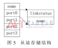
When calculating the slave topology structure, the connection information of each slave is sequentially stored in a struct array, and then the calculation starts from the first slave in the array. For each slave, the name of its upper-level slave is first recorded in port0. Then, the connection status of the slave’s various ports is scanned in the order of port3, port1, and port2. If a port is in a connected state and its child node has not been recorded, the slaves in the array that follow port0 with no value are its child nodes. At this point, the next level is entered, and the connection status of the child nodes is recursively calculated. When the calculation is complete, the connection status of all slaves is clarified, thus completing the calculation of the slave topology structure.
1.2 Read Slave Information
To complete the configuration of the EtherCAT network, in addition to obtaining the topology structure of the slaves, it is also necessary to gather the device information of each slave. In traditional schemes, slave information is provided by the ESI file, while in this scheme, the master accesses the EEPROM of the slaves to obtain the configuration information. This section will introduce how the master reads the device information of the slaves in the SII-based configuration scheme.
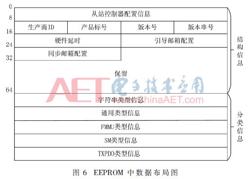
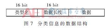
The information structure in EEPROM is shown in Figure 6, where addresses 0 to 64 store the slave structure information, and from address 64 onwards, classification information is stored[9]. All classification information uses the same data structure, but the length is variable. The data structure for classification information is shown in Figure 7, which includes 2 bytes for information type, 2 bytes for data length, and data content of specified length.
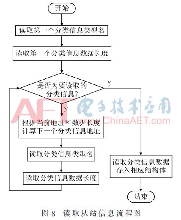
In the SII-based configuration scheme, the master reads slave information according to the process shown in Figure 8. When the master reads the classification information of the slaves, it starts from the first classification information, looks up the information to be read based on the type name until the desired information is found, and stores the information in the corresponding structure.
1.3 Generate Network Information
EtherCAT directly uses standard Ethernet data frames, where the data area of the Ethernet frame consists of one or more EtherCAT sub-messages, each containing the address and data of the slave. In the EtherCAT network, the master and slaves interact through data frames, and the EtherCAT data frame adopts a serial forwarding method, with each EtherCAT data frame passing through all slaves. When a data frame reaches a certain slave, the slave extracts data from the EtherCAT data frame or writes data into the EtherCAT data frame based on the address and command in the EtherCAT data frame. As mentioned above, the master must know the address of the slave to access it, and to interact with the slave, the data area mapping of the slave must be set up.
The allocation of EtherCAT slave addresses mainly involves configuring device addresses and logical addresses. The device address is a two-byte address used by the master to identify each slave. In this scheme, the device address starts from 0X1000 and increments sequentially according to the connection order, assigning a device address to each slave. The logical address is not defined separately but is the address of the slave data in the master’s data area. When using logical addresses, the Fieldbus Memory Management Unit (FMMU) in the slave maps the local physical storage of the slave to the logical address of the master. During the configuration process of this scheme, the master calculates the data length of the slave and the physical address of the slave based on the process data object (PDO) classification information in the slave EEPROM, then sequentially allocates the corresponding length of storage area in the data area for each slave according to the calculation results, and finally configures the FMMU registers based on the calculation results.
The configuration content of the EtherCAT slave data area mainly involves configuring the Sync Manager (SM) for managing synchronization. SM controls all access to the data area through hardware, ensuring that the data area is not accessed simultaneously by both parties, thus guaranteeing the consistency and safety of data exchange between the master and slave applications. During the configuration process of this scheme, the master reads the SM type information from the slave EEPROM, calculates the address, size, and control mode of the SM control data area, and configures the corresponding registers.
2 Scheme Testing
To verify the feasibility of the scheme, a simplified EtherCAT master using the SII configuration scheme was implemented on the Ubuntu platform. This simplified EtherCAT master can complete the configuration of the slaves and the data exchange between the master and slaves. The structure of the testing system is shown in Figure 9.
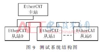
The testing system includes six EtherCAT slaves produced by BECKHOFF, namely EK1100, EL1008, EL2008, EL3054, EL4024, and EK1110. Among them, EL1008 and EL3054 are digital input and analog input, respectively, while EL2008 and EL4024 are digital output and analog output, respectively.
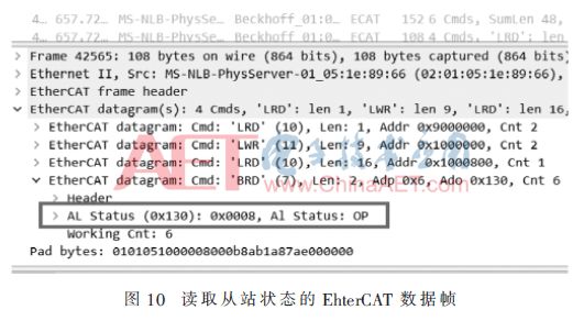
In the testing, the success of the EtherCAT network configuration was judged by checking the status of all slaves and the periodic data exchange function. To facilitate the analysis of slave status, Wireshark was used to capture EtherCAT data frames to analyze the status of the slaves, and the captured data frames are shown in Figure 10. The data in the box of Figure 10 shows the status of the slaves obtained, indicating that all slaves are in OP status, confirming that the slave status transition was successful, and this scheme successfully configured the EtherCAT network.
3 Conclusion
The currently common EtherCAT network configuration schemes use XML files as configuration information, which leads to complex development and low efficiency. To address these shortcomings, this paper studies the configuration process of the EtherCAT network and proposes a configuration scheme based on the SII interface. This scheme uses the information provided by the slave SII interface to calculate and generate the EtherCAT network configuration scheme. Compared with other common schemes, the EtherCAT network configuration scheme based on the SII interface is easy to implement, can improve configuration efficiency, and is relatively easy to realize, thus having high application value.