Made in China 2025 is the first decade action plan for the Chinese government to implement the strategy of becoming a manufacturing power, which is a major strategic deployment to comprehensively improve the quality and level of China’s manufacturing industry. It clearly points out the important position of innovative technologies surrounding industrial robots. Currently, industrial robot technology has been widely applied in fields such as automotive processing, food sorting, and automated production assembly. Industrial communication technology is one of the core technologies of intelligent manufacturing. With the rapid development of intelligent manufacturing, higher requirements have been put forward for the real-time performance, reliability, and communication bandwidth between nodes. The industrial Ethernet master station can run on multiple platforms as long as the hardware provides a standard network port. Therefore, a low-cost, simple, flexible, and high-speed embedded platform can be used as an industrial Ethernet master station, providing a new networked, informational, and intelligent solution.
The traditional hardware platform uses dsp for image processing, which has a slower processing speed and cannot meet the real-time requirements of image processing, thus limiting the application of machine vision. FPGA, as a hardware platform for digital image processing, has advantages such as high speed, high integration, and strong reliability. In order to improve the quality of images and enhance the real-time processing of images by the system, this paper proposes a vision servo control system for a six-degree-of-freedom robot based on Zynq, integrating the camera into the Zynq master station, which improves the real-time performance of the vision servo. Tests have shown that this platform can respond timely to changes in visual detection targets, providing a practical solution for industrial automation.
This paper studies industrial robots based on machine vision, and the main work includes the following points:
(1) Designed the overall scheme of the vision servo control system for the six-degree-of-freedom robot based on Zynq. Using ESR6B robot, Zynq, and camera as the hardware foundation, a six-degree-of-freedom robot vision platform was built.
(2) Designed a vision detection scheme based on FPGA. Using Xilinx provided HLS and CV libraries to process the pixel stream captured by the camera in real-time, and designed a sequence process for identifying the coordinate positions of objects, allowing the Zynq master station to read the object coordinates in real-time. The processed images are output to the display via the HDMI interface.
(3) Completed the position control of the servo for the Zynq using the Zynq PL layer to transmit and receive the Zynq Ethernet frames and calibrate the master station clock, running the bare-metal program of Sum on the PS layer, and transplanting the inverse kinematics algorithm of the six-degree-of-freedom serial robot into the master station code for real-time tracking control of the robot’s end position based on visual feedback.
(4) Experiments verified the accuracy and real-time performance of the object recognition design, and practical motion control experiments were conducted using the independently developed six-degree-of-freedom serial robot. Experiments proved that the robot can follow the movement of objects displayed on the screen in real-time.
The difficulty of this design lies in how to improve the real-time performance of vision detection and robot motion control. Innovatively, the design utilizes the Xilinx Zynq heterogeneous processor, using FPGA as the main unit for vision processing, and transplanting the Zynq master station to the Zynq platform. This allows for real-time vision detection and motion control to be completed on a single chip. This design uses HLS for vision processing, optimizing the code, resulting in a total delay of only 18.6ms for the entire vision processing module. At the same time, in terms of communication, this design uses FPGA for the transmission and verification of the Zynq frames, ensuring that the DC synchronization cycle jitter is stabilized to less than 1U time. Real-time vision detection and motion control have broad applications in industrial robot vision servo. This experiment integrates the camera into the Zynq master station applied to the independently developed six-degree-of-freedom serial robot, embedding the robot kinematics algorithm into the Zynq master station, enabling the robot to make real-time movements following the objects detected by the camera. Experimental results show that the real-time performance of this design far exceeds that of the PC platform for vision processing, and achieves real-time visual following motion along the robot’s X-axis direction.
1. Design of ESR6B Robot Hardware System
The ESR6B robot is an independently developed robot, a typical multi-degree-of-freedom serial robot, as shown in Figure 2-1.
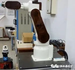
Figure 2-1 ESR6B Robot Body
The vision-guided robot hardware system mainly consists of the robot body, console, Zynq, and visual hardware, as shown in Figure 2-2.
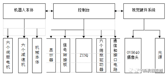
Figure 2-2 Overall System Scheme
2. Basic Design Parameters of ESR6B Robot
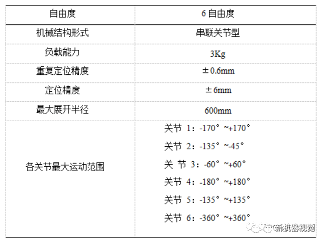
The robot has 6 degrees of freedom, and its main technical parameters include degrees of freedom, load capacity, repeat positioning accuracy, positioning accuracy, and workspace. These parameters are the main indicators reflecting the performance of the robot.
The basic technical parameters of the ESR6B robot are shown in Table 2-1.
3. Building the Robot Vision System Hardware Platform
The choice of hardware for the robot vision system directly affects image acquisition, image quality, and subsequent processing, and impacts the real-time performance of the entire control system. Therefore, hardware should be strictly selected based on requirements and performance. The six-degree-of-freedom robot vision servo control system based on Zynq mainly includes modules for camera, Zynq, storage, display, and communication.
The Zynq is a heterogeneous chip designed by Xilinx, containing both FPGA and ARM. The Zynq system-on-chip integrates a processing system (PS) based on ARM and programmable logic units (PL). The Zynq master station and the Linux operating system run on the PS side, while image algorithms are accelerated in hardware on the FPGA, placed on the PL side. Through the AXI bus interconnect technology, the FPGA is integrated with the arm, fully leveraging the advantages of both device structures.
The main characteristic parameters of the camera include resolution, frame rate, and color space. Based on these characteristics, a camera that meets experimental requirements is selected. In this system design, the model selected is OV 5640, a CMOS-type digital image sensor that supports output of images with a maximum of 5 million pixels (2592×1944) resolution, supports VGA timing output of image data, and the output data format supports YUV (422/420), YCbCr 422, RGB 565, and JPEG formats. This design uses the RGB 565 format for data reading.
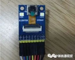
Figure 2-3 OV 5640 Camera
In this design, image data is captured by the OV 5640 camera, and then pre-processed and coordinate-detected by the FPGA. The data stream goes through VDMA into DDR 3 memory via the HP0 port, and then returns via HP0, going through VDMA, and finally outputting video via the HDMI interface.
The main parameters of the light source include contrast, brightness, surface texture, and light source uniformity. Based on the characteristics of the light source, a ring light source from Shanghai Dongguan Technology, model Rin-90-6R-10 W, with white LED as the light source, is selected. The physical object is shown in Figure 2-4.
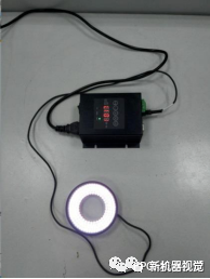
Figure 2-4 Physical Image of Ring Light Source
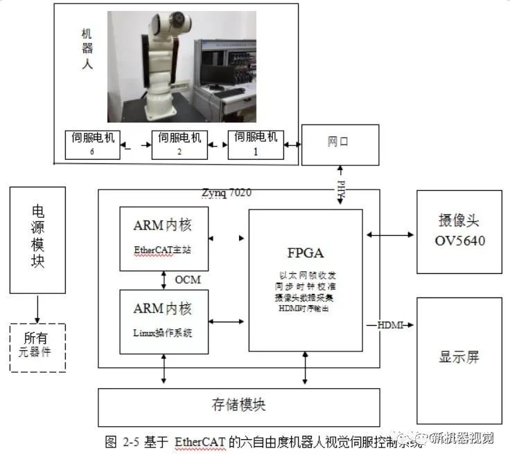
The vision servo control system for the six-degree-of-freedom robot based on Zynq is shown in Figure 2-5.
Analysis of Vision Servo Performance
Vision servo requires a very short delay between target recognition and control to reflect the real-time nature of control. This paper designed a set of comparative experiments, where scheme one uses the Zynq board with an integrated camera as the Zynq master station, and scheme two connects a PC to a USB camera and uses advertisement to transmit coordinate data to the TwinCAT master station. Both schemes use the same image processing algorithm, and both master stations operate in CSP mode.
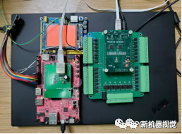
Figure 4-5 Performance Testing Platform
The delay calculation platform consists of STM 32 + TFT color screen and the XMC 4300 based Zynq stepper slave. When the screen starts to refresh red, the timer starts counting. When the pulse from the stepper slave is received, the timing stops. The delay comparison between scheme one and scheme two (unit we) is shown in Figure 4-6.
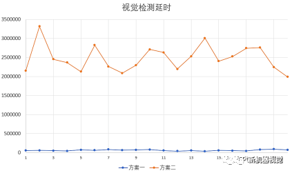
Figure 4-6 Comparison of Schemes
It can be seen that the detection delay of this design averages only 58 milliseconds, while scheme two takes as long as 2.48s. Under the same image detection algorithm, the FPGA has lower delay, and due to the direct integration of the camera into the master station board, the image transmission delay is lower, and the cost is lower.
Source: New Machine Vision
Disclaimer: This article is a network reprint, and the copyright belongs to the original author. However, due to numerous reprints, it is impossible to confirm the true original author, so only the source of reprint is indicated. If the videos, images, and texts used in this article involve copyright issues, please inform us immediately, and we will confirm the copyright based on the proof materials you provide and pay the remuneration according to national standards or delete the content immediately! The content of this article reflects the views of the original author and does not represent the views of this public account, nor does it take responsibility for its authenticity.