Abstract:
EtherCAT is one of the widely used field buses in the industrial control field. The slave controller ESC (EtherCAT Slave Controller) is the key to implementing EtherCAT protocol data communication in slave modules. Achieving autonomous control over slave control chips is an important foundation for the localization and research and development of industrial control systems. Based on the EtherCAT communication protocol and basic communication functionality logic, FPGA state machines for key communication nodes such as EBUS encoding/decoding, Auto-forwarder, and Loop-back function were designed. By analyzing the data state changes at each stage, the correctness of the communication data at each node was verified. Experimental results show that the FPGA implementation of the basic communication link for EtherCAT slave is completely feasible.
Citation Format in Chinese: Ma Baoquan, Yao Wangjun, Liu Yunlong, et al. Analysis and verification of EtherCAT slave controller communication link based on FPGA[J]. Application of Electronic Technique, 2017, 43(8): 95-99.Citation Format in English: Ma Baoquan, Yao Wangjun, Liu Yunlong, et al. Analysis and verification of EtherCAT slave controller communication link based on FPGA[J]. Application of Electronic Technique, 2017, 43(8): 95-99.
0 Introduction
EtherCAT is one of the field buses widely used in industrial control proposed by BECKHOFF. This bus has a full-duplex working mode and can achieve data transmission based on the master (Master) and slave (Slave) connection mode, featuring low latency and high security. The EtherCAT slave controller ESC (EtherCAT Slave Controller) is the key to implementing the EtherCAT communication protocol in slave modules. Currently, domestic communication functions based on the EtherCAT protocol mainly use slave chips such as ET1100/ET1200 to implement[1-4]. However, these types of chips not only have basic communication functions but also possess many other functions, and the additional communication mechanisms are not disclosed to technicians in China, resulting in an inability to achieve complete autonomous control over such communication chips, making it impossible to discuss the enhancement of system security through effective security mechanisms. With the increasing prominence of information security issues in the industrial control field, the application of such uncontrollable communication chips introduces certain security risks to the operation of core control systems in China. To achieve complete autonomous control over communication chips used in control systems, the autonomous development of the EtherCAT communication protocol based on FPGA is very necessary, and it is also an important prerequisite for enhancing the security capability of communication systems through independent security mechanisms.
The basic communication link is the core to achieve the transmission and reception of EtherCAT protocol data. Therefore, this study is based on the characteristics of the EtherCAT protocol and data transmission mechanism, designing FPGA state machines for key communication nodes to verify the feasibility of the basic communication link function of the EtherCAT slave controller, laying an important foundation for improving other communication functions and security mechanisms of EtherCAT.
1 EtherCAT Slave Controller Framework
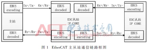
The communication link between the EtherCAT master and each slave is shown in Figure 1. During the communication process, data frames traverse all slave devices. When a data frame passes through a certain slave, the slave device analyzes the addressing message according to the message command and reads/writes data to the specified location. After the data frame reaches the last slave, that slave sends the processed data frame back to the master. The master processes the returned data after receiving this uplink telegram, completing one communication session[5-6].
The EtherCAT slave controller mainly includes the data frame processing unit, EBUS interface encoding/decoding module, Auto-forwarder module, Loop-back function module, etc. Taking the ET1100/ET1200 slave controller as an example, its internal framework is shown in Figure 2, mainly including MII, EBUS interface, EtherCAT data frame processing unit, Fieldbus Memory Management Unit (FMMU), SyncManager, distributed clock, PDI interface, ESC address space (including registers and user data memory), EEPROM control, as well as status control, interrupts, watchdog, and physical layer management.
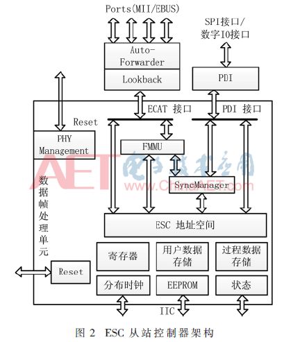
The frame processing unit analyzes and processes the EtherCAT data stream. The Fieldbus Memory Management Unit (FMMU) is one of the core modules in the EtherCAT slave controller IP core, used to realize the logical addressing of the slave by the master. The SyncManager facilitates the exchange of local application data between the master and the slave. Both EtherCAT frames and the PDI interface must be polled by the processor to determine whether the other side has completed access. The PDI interface module is the application data interface of the ESC chip.
In the process of implementing the EtherCAT slave controller in FPGA, if the data link can be established, the data frame can be transmitted through the EBUS and MII interfaces to the FPGA, where the FPGA will identify the data frame, perform CRC verification, unpack the EtherCAT frame format and protocol commands, and send the data frame based on the port connection status. This indicates that the EtherCAT slave controller can be autonomously developed and implemented in FPGA. In the above data link, the EBUS interface involves the EBUS module, which mainly parses the EBUS protocol and receives or transmits data through Manchester encoding/decoding; the FPGA identifies the data frame and performs CRC verification through the Auto-Forwarder module; and sends the data frame through the Loop-back function module. The implementation process of each of these modules will be introduced below.
2 Module Implementation Logic
2.1 EBUS Encoding/Decoding Module
For the EBUS implementation method, the LVDS signal data rate of the EBUS interface is 100 Mb/s, and the EBUS interface uses Manchester encoding/decoding to achieve this via LVDS.
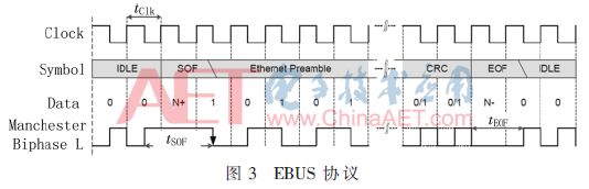
When implementing the EBUS section, according to the requirements of the EBUS protocol, both Manchester decoding and Manchester wave encoding need to be implemented. In which “0” is represented by “01” and “1” by “10”. The EBUS protocol is divided into idle identifier, start frame identifier (SOF), and end frame identifier (EOF). The idle identifier is “0”, the start frame identifier consists of three consecutive clocks (200 MHz) of “1”, and the end frame identifier consists of three consecutive clocks (200 MHz) of “0”. The EBUS protocol is shown in Figure 3.
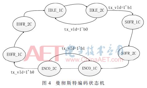
The state machine for Manchester encoding is shown in Figure 4, which is divided into eight states: initial state 1 (IDLE_1C), initial state 2 (IDLE_2C), frame start state 1 (SOFR_1C), frame start state 2 (SOFR_2C), encoding state 1 (ENCO_1C), encoding state 2 (ENCO_2C), end frame state 1 (EOFR_1C), and end frame state 2 (EOFR_2C), with a processing clock of 200 MHz.
The description of each state is as follows:
IDLE_1C is the initial state 1, corresponding to sending the idle identifier of the EBUS protocol, sending data is ‘0’. The next clock will enter IDLE_2C state.
IDLE_2C is the initial state 2, corresponding to sending the idle identifier of the EBUS protocol, sending data is ‘1’. When the sent data is valid, it enters SOFR_1C state; otherwise, it enters IDLE_1C state.
SOFR_1C is frame start state 1, corresponding to sending the start frame identifier of the EBUS protocol; the next clock will enter SOFR_2C state.
SOFR_2C is frame start state 2, corresponding to sending the start frame identifier of the EBUS protocol; the next clock will enter ENCO_1C state.
ENCO_1C is encoding state 1, corresponding to sending frame data; the next clock will enter ENCO_2C.
ENCO_2C is encoding state 2, corresponding to sending frame data; when the sent data is invalid, it enters EOFR_1C state; otherwise, it enters ENCO_1C state.
EOFR_1C is end frame state 1, corresponding to sending the end frame identifier; the next clock will enter ENCO_2C state.
EOFR_2C is end frame state 2, corresponding to sending the end frame identifier; at this point, one frame of data has been sent, and the next clock returns to IDLE_1C state.
The state machine for Manchester decoding is shown in Figure 5, which is divided into five states: initial state (IDLE), frame start state (SOFR), encoding state 1 (ENCO_1C), encoding state 2 (ENCO_2C), and end frame state (EOFR), with a processing clock of 200 MHz.
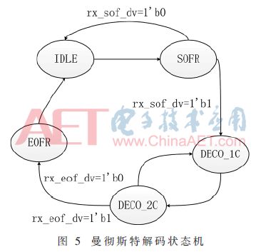
The description of each state is as follows:
IDLE is the initial state, corresponding to receiving the idle identifier of the EBUS protocol; the next clock will enter SODR state.
SOFR is the frame start state, corresponding to receiving the start frame identifier of the EBUS protocol. When three consecutive ‘1’s are received, rx_sof_dv becomes 1, and the next clock enters ENCO_1C state; otherwise, it enters IDLE state.
ENCO_1C is encoding state 1, corresponding to receiving frame data; the next clock will enter ENCO_2C.
ENCO_2C is encoding state 2, corresponding to receiving frame data; when three consecutive ‘0’s are received, it enters EOFR state; otherwise, it enters ENCO_1C state.
EOFR_1C is the end frame state, indicating that a complete EtherCAT frame has been received; the next clock will enter IDLE state.
2.2 Auto-forwarder Module
The Auto-forwarder module is the first processing module that MII and EBUS modules enter into IPCORE, mainly implementing MII/EBUS data buffering, detecting frame preambles, error detection, and sending data to the Loop-back function and EtherCAT Processing Unit. The Auto-forwarder module implements the MII/EBUS data buffering function by storing EtherCAT frame data in FIFO and reading data out after processing with IPCORE clock (25 MHz), achieving synchronization of frame data with IPCORE clock before entering the next module for processing. Detecting the frame preamble occurs when frame data is valid; by detecting the frame preamble (0x55555555555555555D), it is confirmed that this frame is an Ethernet frame. Data detection mainly checks for three types of errors: physical layer errors (RX errors), data frame errors, and CRC errors. After data synchronization through FIFO, under Ethernet frame conditions, CRC verification is performed. If the CRC check is correct, the frame data is sent to the Loop-back function or EtherCAT Processing Unit; if the CRC check is incorrect, the frame is discarded. Sending data to the Loop-back function and EtherCAT Processing Unit occurs under the conditions of correct CRC verification and no other errors. The state machine of the Auto-forwarder module is shown in Figure 6.
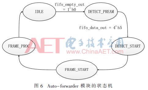
The state machine of the Auto-forwarder module is divided into five states: initial state (IDLE), detecting preamble state (DETECT_PREAM), detecting preamble start state (DETECT_START), frame start state (FRAME_START), and frame processing state (FRAME_PROC), with a processing clock of 25 MHz. The descriptions of each state are as follows:
IDLE is the initial state. When there is no frame data, the state remains in IDLE. When frame data is detected as 5, it transitions to DETECT_PREAM state.
DETECT_PREAM is the detecting preamble state. When the frame receives the preamble 5 and detects D, it transitions to DETECT_START state.
DETECT_START is the detecting preamble start state. In the next clock, it transitions to FRAME_START state.
FRAME_START is the frame start state, where frame data reception begins. In the next clock, it transitions to FRAME_PROC state.
FRAME_PROC is the frame processing state, where frame data is formally processed. When there is no frame data, it transitions to IDLE state.
2.3 Loop-back Function Module
The Loop-back function determines the data frame forwarding state based on the port’s open status. IPCORE has four ports. If the current port is closed or not connected, the Loop-back function forwards EtherCAT frames to the next logical port. The loop-back function of port 0 (PORT0) will forward frame data to the data frame processing unit. The port statuses are: auto-close and manual open. The processing order of data frames from different ports is as follows:
(1) 0 → EtherCAT Processing Unit → 0
(2) 0 → EtherCAT Processing Unit → 1 / 1 → 0
(3) 0 → EtherCAT Processing Unit → 1 / 1 → 2 / 2 → 0 (log. ports 0, 1, and 2) or 0 → EtherCAT Processing Unit → 3 / 3 → 1 / 1 → 0 (log. ports 0, 1, and 3)
(4) 0 → EtherCAT Processing Unit → 3 / 3 → 1 / 1 → 2 / 2 → 0
For verification and testing purposes, this paper focuses on the data forwarding function and testing in the dual-port case.
3 Functional Testing
To conduct system testing on the communication link based on FPGA, a test environment as shown in Figure 7 was set up.
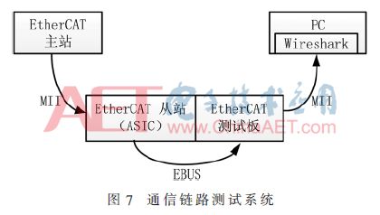
Here, the EtherCAT master refers to the Beckhoff EtherCAT master, which can send specified EtherCAT frames to the slave; the EtherCAT slave (ASIC) refers to the Beckhoff EtherCAT slave based on the ET1100 chip. The EtherCAT master sends EtherCAT frames to the EtherCAT slave (ASIC) through MII signals, and the EtherCAT slave (ASIC) converts the EtherCAT frames into EBUS signals, transmitting data to the EtherCAT test board; the EtherCAT test board is a test board based on FPGA.
In the test, the test board transmits the data frame to the FPGA through the EBUS interface, where the FPGA decodes the data frame, identifies it, performs CRC verification, unpacks the EtherCAT frame format and protocol commands. The data is then forwarded to a PC via MII, where Wireshark is used to capture and verify the correctness of the data frame.
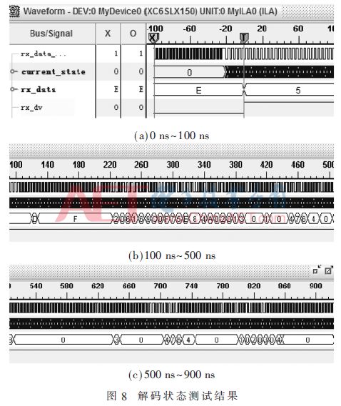
3.1 Decoding State Test
The decoding state test results are shown in Figure 8, where rx_data_interal is the differential to single-ended signal of EBUS, current_state is the state machine signal, rx_dv is the data valid signal, and rx_data is the received data. It can be seen that the LVDS signal of the EBUS protocol is processed through the state machine after differential to single-ended conversion to obtain the frame data.
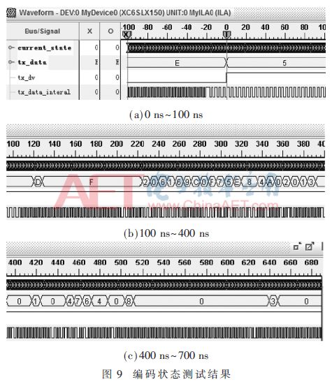
3.2 Encoding State Test
The encoding state test results are shown in Figure 9, where tx_data_interal is the single-ended signal converted to EBUS differential signal, current_state is the state machine signal, tx_dv is the data valid signal, and tx_data is the sent data. It can be observed that after the sending data is valid, the state machine converts the data from single-ended to differential for transmission.
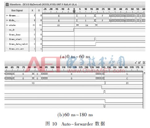
3.3 Auto-forwarder Data State
The data after passing through the Auto-forwarder state is shown in Figure 10, where frame represents the frame data, fifo represents the data synchronized through FIFO, state represents the state machine signal, frame_done is the end signal of the data frame, frame_start is the start signal of the frame, frame_data_valid is the valid signal of the data frame, and frame_crc_err is the error signal of the frame. The results indicate that the data frame can be correctly identified and parsed; after the frame ends, frame_crc_err can be seen to have a low signal.
3.4 Data Frame Verification
The results captured by Wireshark indicate that the data frame can be correctly processed by the FPGA, and the captured packets are correctly received as EtherCAT type forwarded packets, indicating that the data link has been established.
4 Conclusion
This article verifies the correctness of the FPGA state machines for EBUS encoding/decoding, Auto-forwarder, and Loop-back function modules on key communication links by analyzing the data results at each stage, indicating that the FPGA implementation of the basic communication link for EtherCAT slave is completely feasible, creating conditions for the development of a complete ESC slave controller.
References
[1] Wang Lei, Li Muguo, Wang Jing, et al. Research on EtherCAT protocol field-level real-time Ethernet control system[J]. Computer Engineering and Design, 2011, 32(7): 2294-2297.
[2] Li Muguo, Wang Lei, Wang Jing, et al. Industrial Ethernet data acquisition system based on EtherCAT[J]. Computer Engineering, 2010, 36(3): 237-239.
[3] Shan Chunrong, Liu Yanqiang, Xun Ji. Design of industrial Ethernet fieldbus EtherCAT and driver programs[J]. Manufacturing Automation, 2007, 29(11): 79-82.
[4] Shi Dafang, Liu Jianlin, Wang Hui, et al. Design of a high-performance EtherCAT real-time Ethernet slave[J]. Journal of Hunan Normal University (Natural Science), 2011, 34(3): 37-40.
[5] Ma Junxian, Zhou Dong, Yang Zhijia, et al. Design and implementation of EtherCAT slave[J]. Bus and Network, 2011(8): 37-40.
[6] Hu Shijiang. Design of EtherCAT real-time industrial Ethernet slave based on ET1100[J]. PLC & FA, 2009(11): 67-70.
Author Information:
Ma Baoquan1,2, Yao Wangjun1,2, Liu Yunlong1,2, Zhang Xiaoli1,2, Huang Bing1,2, Zhao Dezheng1,2
(1. National Engineering Laboratory for Information Security Technology of Industrial Control Systems, Beijing 100083; 2. North China Computer System Engineering Research Institute, Beijing 100083)