We often encounter situations where a company, as employees or departments increase, adds a router, creating two subnets, with subnet A and subnet B on different segments. When there are multiple routers in the network, it is required that the subnets under different routers can communicate with each other and also access the internet through a broadband router. How can this be achieved? In this issue, we will use router operations to implement three case scenarios.
Case Scenario 1
The company accesses the internet through a router R1, and the local area network LAN1. Due to business needs, an additional router R2 is added, creating a new local area network segment LAN2.
To enable PC1 and PC2 to communicate with each other, the following settings can be made as shown in the diagram.
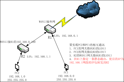
To achieve mutual communication between PC1 and PC2, the following settings can be made:
1. Set the gateway of PC1 to R1’s LAN
2. Set the gateway of PC2 to R2’s LAN port
3. Set R2’s WAN port gateway to R1’s LAN port
4. Specify a static route on R1, forwarding the destination IP in the 192.168.1.x subnet to R2.
The static route configuration for R1 is explained separately:A static route generally consists of three parts: destination IP address, subnet mask, and next hop (gateway) address. According to the analysis in the above diagram, the information included in creating a new static route should have the following content: the next hop address for the IP packets destined for the 192.168.1.0 subnet (with a subnet mask of 255.255.255.0) is 192.168.0.100. The specific configuration location, for example, in a TP-Link router, is configured in the static route table:
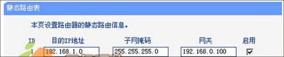
When setting a static route, the gateway IP must belong to the same subnet as the LAN port IP of this router.
If the destination IP address is the IP address of a host, the subnet mask must be 255.255.255.255
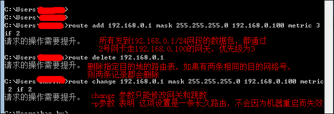
If it is on a server, static routes can be configured through the command line, including adding, deleting, and modifying.
It can be seen that Case 1 is actually very similar to the bridging principle of routers.
Case Scenario 2
A residential community shares broadband access. User A builds a local area network with a broadband router, and User B also builds a local area network with a broadband router. The hosts in User A and User B’s local area networks cannot communicate with each other. The network topology is as follows:
To achieve mutual access between PC2 and PC1, it seems similar to Case 1, requiring the addition of two static routes in the internal network gateway. Generally, the community gateway will not allow users to configure routes casually, and such configuration will allow computers from other subnets to access PC1 and PC2.
Method for two routers on different subnets to communicate:
Set the WAN ports of the two routers to the same subnet, as shown in the diagram:
Router 1 WAN port IP: 10.1.1.3 Router 2 WAN port IP: 10.1.1.3
The LAN ports of the two routers can be set arbitrarily as long as they are not in the same subnet as the WAN ports.
Case Scenario 3
Cases 1 and 2 are both about two routers, while for scenarios with multiple routers and multi-level routing devices in the network, this can be seen as a combination of scenarios one and two.
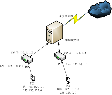
Similar network topology is as follows: three routers
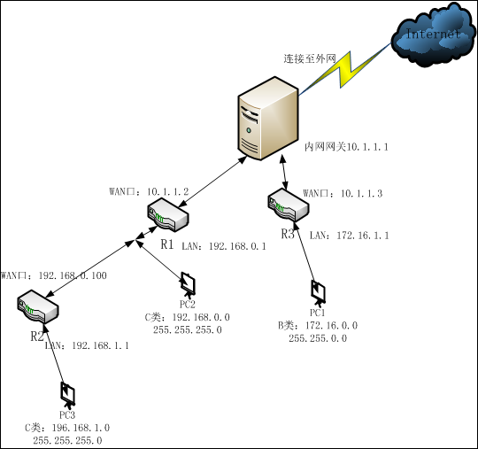
To achieve mutual access between PC1, PC2, and PC3, it is necessary to configure static routes between Router 1 and Router 3. So how should this be configured?
In fact, it just integrates the situations from Case 1 and Case 2, which is Case 3.
Analysis: (Here routers are represented by R)
R1 is between R2 and R3, R1 is connected to PC2. To achieve mutual access between PC2 and PC1, PC3, the destination addresses for R1 are PC1 and PC3.
And the next hops for R1 are R2 and R3. The WAN port of R2 is connected to the LAN port of R1, so the LAN port address of R1 and the WAN port address of R2 are in the same subnet, while the WAN port address of R1 and the WAN port of R3 are in the same subnet.
So for R1:
Destination address is 192.168.1.0, mask 255.255.255.0, next hop (gateway) is 192.168.0.100
Destination address is 172.16.0.0, mask 255.255.0.0, next hop (gateway) is 10.1.1.3
So for R3:
Destination address is 192.168.0.0, mask 255.255.255.0, next hop is 10.1.1.2
Destination address is 192.168.1.0, mask 255.255.255.0, next hop is 10.1.1.2.
If the above is not understood, you can look at it from another perspective:
For router R3, it can only see R1 and not R2, so for R3, the two routes from R1 and R2 above can be summarized into one, which is
Destination address is 192.168.0.0, mask is 255.255.0.0, next hop is 10.1.1.2, this subnet includes all subnets from 192.168.0.0 to 192.168.255.0, including R1 and R2. This static route will forward all IP packets destined within this range to router R1 at 10.1.1.2. This process, where multiple sub-route entries are summarized into one encompassing route entry, is calledroute summarization.
Why is it important to write subnet masks precisely in a network?
In large routers, the routing table is often very long and large. Using route summarization can reduce the length of the routing table and improve router efficiency.
Of course, route summarization is not always effective, as subnetting is arbitrary, and other segments in the route summarization may exist under other local area networks. Reckless summarization may lead to errors, so in actual projects, we must calculate the subnet mask very precisely, which is why the author previously advised against directly setting Class B addresses with a subnet mask of 255.255.0.0.
The route summarization in Case 3 can be set more precisely, for 192.168.0.0 and 192.168.1.0, the network bits that are the same have the first 23 bits. To distinguish these two subnets through the mask, the mask needs to be set to 255.255.254.0, rather than 255.255.0.0. The improved summarized routing table should be written as follows:
Destination address is 192.168.0.0, subnet mask is 255.255.254.0, next hop is 10.1.1.2, this summarized route will only include the two subnets 192.168.0.0 and 192.168.0.1, which is a precise route. This helps with future network expansion and maintenance.
END
This article is complete.