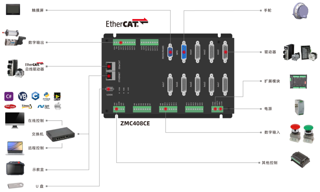
ZMC408CE supports hardware comparison output for 8 channels, hardware timers, and precise output during motion, as well as 8-channel PWM output, corresponding to output ports OUT0-7, supporting simultaneous triggering of hardware comparison output for 8 channels.
ZMC408CE Video Introduction
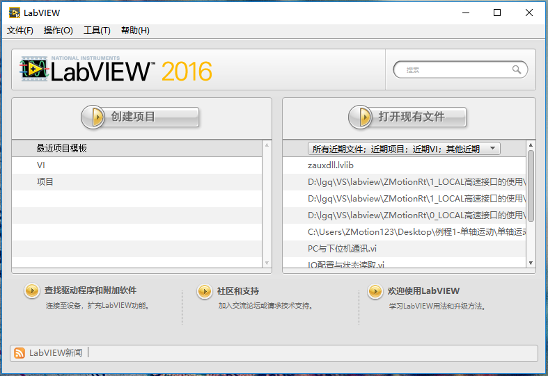
1. Create a LabVIEW project.
2. Download the LabVIEW Vi function library folder “zauxdll” from the “CD materials” to your computer, then copy it to the LabVIEW installation path under LabVIEW/user.lib.

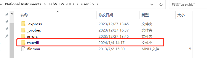
Zauxdll function library paste path
3. Introduction to relevant PC functions.
|
Command 3 |
|
||||
|
Command prototype |
int32 __stdcall ZAux_OpenEth(char *ipaddr, ZMC_HANDLE * phandle) |
||||
|
Command description |
Ethernet connection to the controller. |
||||
|
Input parameters |
|
||||
|
Output parameters |
|
||||
|
Return value |
Returns 0 on success, non-zero values refer toerror codesdescription. |
||||
|
Command example |
Connect the controller via Ethernet |
||||
|
Detailed description |
1. The Ethernet port uses RJ45 standard cable, with a communication speed of 100Mbit/s. 2. The factory default IP address of the controller is 192.168.0.11, and the port number is 502. The communication device on the opposite side must be in the same subnet as the controller to connect. 3. The most commonly used method to connect the controller. 4. ZMC_HANDLE type: A specific data definition type used for connecting to the control card in the Zmotion library; |
|
Command 228 |
|
||||||||
|
Command prototype |
int32 __stdcall ZAux_Direct_GetTable(ZMC_HANDLE handle, int tabstart, int numes, float *pfValue) |
||||||||
|
Command description |
Read data from the TABLE. |
||||||||
|
Input parameters |
|
||||||||
|
Output parameters |
|
||||||||
|
Return value |
Returns 0 on success, non-zero values refer toerror codesdescription. |
||||||||
|
Command example |
Usage of Table register |
||||||||
|
Detailed description |
It is a large array built into the controller, with a data type of 32-bit floating point (64-bit floating point for series 4 and above), not saved when powered off. |
|
Command 27 |
|
||||||
|
Command prototype |
int32 __stdcall ZAux_Direct_GetDpos(ZMC_HANDLE handle, int iaxis, float *pfValue) |
||||||
|
Command description |
Read the current position of the axis or the desired position sent by the controller, unitunits. |
||||||
|
Input parameters |
|
||||||
|
Output parameters |
|
||||||
|
Return value |
Returns 0 on success, non-zero values refer toerror codesdescription. |
||||||
|
Command example |
Get basic motion parameters of the axis |
||||||
|
Detailed description |
/ |
|
Command 37 |
|
||||||
|
Command prototype |
int32 __stdcall ZAux_Direct_GetMspeed(ZMC_HANDLE handle, int iaxis, float *pfValue) |
||||||
|
Command description |
Read the current real-time axis feedback speed, unitunits. |
||||||
|
Input parameters |
|
||||||
|
Output parameters |
|
||||||
|
Return value |
Returns 0 on success, non-zero values refer toerror codesdescription. |
||||||
|
Command example |
float fValue; ret = ZAux_Direct_GetMspeed(handle, 0, &fValue); //Read the current feedback speed of axis 0. handle: continuous handle of the controller |
||||||
|
Detailed description |
/ |
|
Command 38 |
|
||||||
|
Command prototype |
int32 __stdcall ZAux_Direct_GetVpSpeed (ZMC_HANDLE handle, int iaxis, float *pfValue) |
||||||
|
Command description |
Read the real-time motion speed of the axis sent by the controller, unitunits/s. |
||||||
|
Input parameters |
|
||||||
|
Output parameters |
|
||||||
|
Return value |
Returns 0 on success, non-zero values refer toerror codesdescription. |
||||||
|
Command example |
float fValue; ret = ZAux_Direct_GetVpSpeed(handle, 0, &fValue); //Read the current command motion speed of axis 0. handle: continuous handle of the controller |
||||||
|
Detailed description |
1. When multiple axes are in motion, the main axis returns the interpolated motion speed, not the individual speed of the main axis. 2. Non-main axes return the corresponding individual speed, consistent with feedback speed effects. 3. The planned speed is designed for displaying the composite speed of multiple axes by default, and it has no negative values unless the value of bit0 of SYSTEM_ZSET(zbasic command, PC can use this function: ZAux_Direct_SetParam(handle, “SYSTEM_ZSET”, axis number, set value))is set to 0, it can be used to display the command speed of a single axis, which can be positive or negative. |
|
Command 29 |
|
||||||
|
Command prototype |
int32 __stdcall ZAux_Direct_GetMpos(ZMC_HANDLE handle, int iaxis, float *pfValue) |
||||||
|
Command description |
Read the measured feedback position of the axis, unitunits. |
||||||
|
Input parameters |
|
||||||
|
Output parameters |
|
||||||
|
Return value |
Returns 0 on success, non-zero values refer toerror codesdescription. |
||||||
|
Command example |
Get basic motion parameters of the axis |
||||||
|
Detailed description |
/ |
|
Command 3 |
|
||||||||||||||
|
Command prototype |
int32 __stdcall ZAux_Direct_Cam(ZMC_HANDLE handle,int iaxis, int istartpoint, int iendpoint, float ftablemulti, float fDistance) |
||||||||||||||
|
Command description |
The electronic cam, the CAM command decides the axis motion based on the data stored in the TABLE. |
||||||||||||||
|
Input parameters |
|
||||||||||||||
|
Output parameters |
/ |
||||||||||||||
|
Return value |
Returns 0 on success, non-zero values refer toerror codesdescription. |
||||||||||||||
|
Command example |
Cam table example routine |
||||||||||||||
|
Detailed description |
Note: Two or more CAM commands can operate simultaneously using the same segment of TABLE data area. The total motion time is determined by the set speed and the fourth parameter, and the actual speed of motion is automatically matched according to the TABLE trajectory and time. TABLE data needs to be set manually, the first data is the guide point, recommended to set as 0. TABLE data * table multiplier this ratio = number of pulses sent. Please ensure that the distance parameter passed by the command * units is an integer number of pulses, otherwise, floating-point numbers will cause slight errors in motion. |
4. Data source acquisition for motion control in LabVIEW.
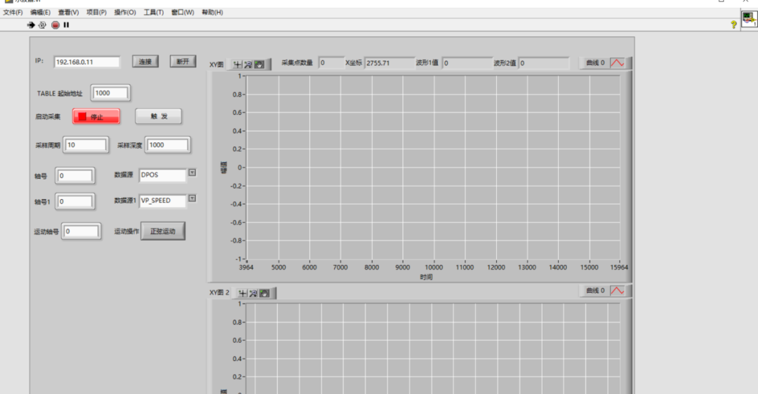
(2) In the program editing box, add a “While loop” in the added frame, and add an “event structure” inside the “While loop”, right-click to select add event branch, select “timeout” event, obtain the current number of sampling points from the data source, and import the data source data into the oscilloscope for waveform display.
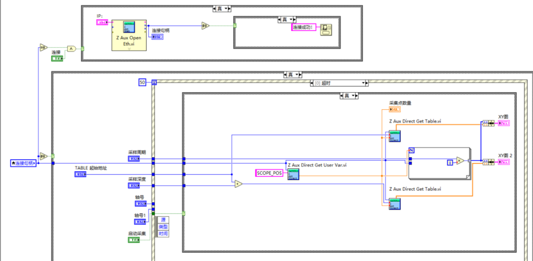
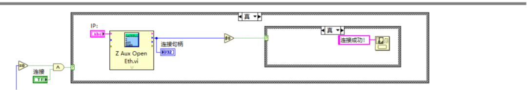
(3) Select the event structure, right-click to select add event branch, in the loop structure, when the handle is empty, automatically obtain the current IP of the controller, then in this event branch use the “Z Aux Open Eth.vi” function to connect to the controller, to achieve the function of connecting the controller button.
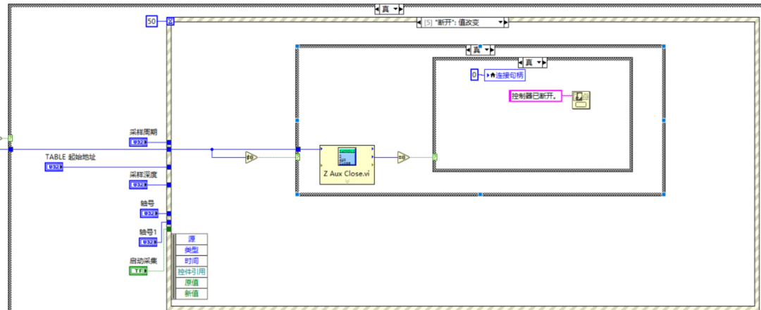
(4) Select the event structure, right-click to select add event branch, select “disconnect” value change, then in this event branch use the “Z Aux Close.vi” function to disconnect from the controller, to achieve the function of disconnecting the link button.
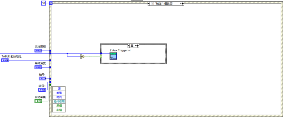
(5) Select the event structure, right-click to select add event branch, select “trigger” value change, then in this event branch use the “Z Aux Trigger.vi” function to trigger the oscilloscope to capture, to achieve the function of triggering command to capture the data source and store the data in the table register.
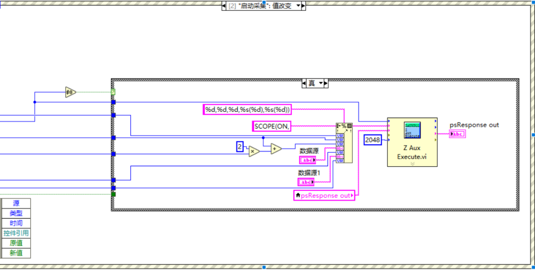
(6) Select the event structure, right-click to select add event branch, select “start acquisition” value change, then in this event branch use the “Z Aux Execute.vi” function to call the command SCOPE to start obtaining data source data, and store it in the table register.
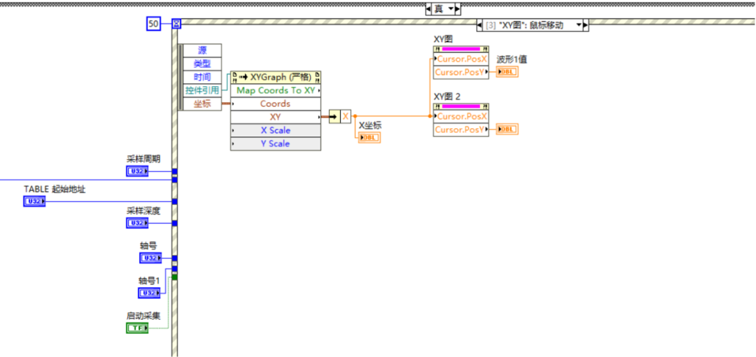
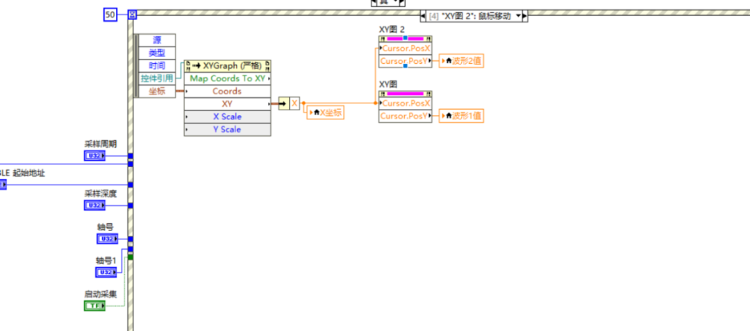
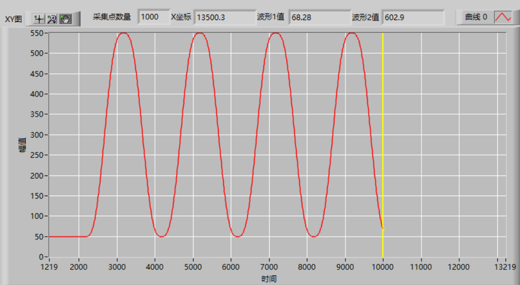
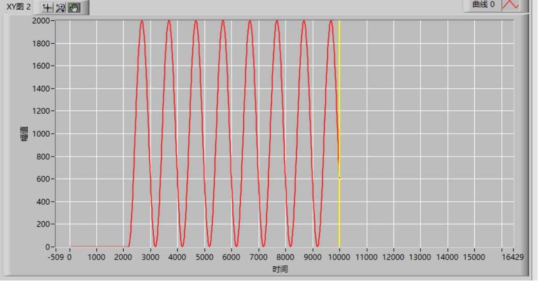
(7) Select the event structure, right-click to select event, select “XY graph:” mouse change, then in this event branch, read the coordinates of the mouse position in the XY oscilloscope and XY2 oscilloscope in real-time and display them on the interface.
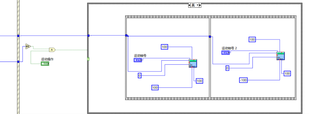
(8) Select the condition structure, when the sine motion button is pressed, trigger the two segments of sine motion using the tiled sequence structure to execute the two segments of electronic cam motion commands in order, using the “Z Aux Cam.vi” function according to the data previously loaded in the table register for corresponding electronic cam motion.
DIM num_p,scale,m,t 'Variable definitionnum_p=100scale=500FOR p=0 TO num_p TABLE(p,((-SIN(PI*2*p/num_p)/(PI*2))+p/num_p)*scale) 'table stores cam table motion parametersNEXT2. The oscilloscope waveform of the ZDevelop software is shown below.
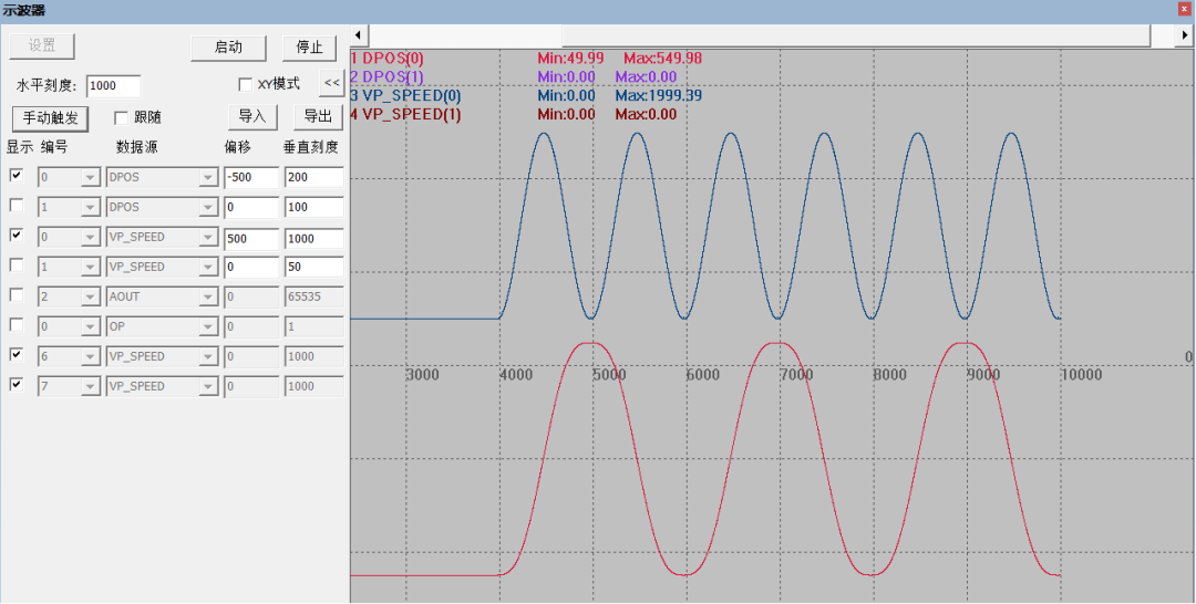
3. The LabVIEW oscilloscope waveform, the oscilloscope data source is the DPOS data content, consistent with the ZDevelop software oscilloscope dpos waveform.
4. The LabVIEW oscilloscope waveform, the oscilloscope data source is the VP_Speed data content, consistent with the ZDevelop software oscilloscope VP_speed waveform.
This time, the EtherCAT motion controller of Positive Motion technology in LabVIEW for motion control and real-time data acquisition is shared here.
For more exciting content, please follow the “Positive Motion Assistant” public account. For related development environment and example code, please consult Positive Motion technology sales engineers: 400-089-8936.
Review Past Content
The Draw is Here! Fans who participated in the “Motion Control System Application and Practice” book giveaway, look here
Book Giveaway! Fully Self-Developed IDE’s “Motion Control System Application and Practice”
Application of EtherCAT Motion Controller on ROS (Part 2)
Application of EtherCAT Motion Controller on ROS (Part 1)
Belt Synchronous Following: EtherCAT Ultra-High-Speed Real-Time Motion Control Card XPCIE1032H PC Host C# Development (Part 14)
Custom Electronic Cam Curve Motion: EtherCAT Ultra-High-Speed Real-Time Motion Control Card XPCIE1032H PC Host C# Development (Part 13)
Continuous Trajectory Processing and Speed Prediction: EtherCAT Ultra-High-Speed Real-Time Motion Control Card XPCIE1032H PC Host C# Development (Part 12)
Introduction to PT/PVT Motion Modes: EtherCAT Ultra-High-Speed Real-Time Motion Control Card XPCIE1032H PC Host C# Development (Part 11)
Project Engineering Download and XML Configuration File Download: EtherCAT Ultra-High-Speed Real-Time Motion Control Card XPCIE1032H PC Host C# Development (Part 10)
EtherCAT Driver Zeroing and Controller Zeroing: EtherCAT Ultra-High-Speed Real-Time Motion Control Card XPCIE1032H PC Host C# Development (Part 9)
2D/3D Multi-Axis PSO Visual Flying and Precise Output: EtherCAT Ultra-High-Speed Real-Time Motion Control Card XPCIE1032H PC Host C# Development (Part 8)
Single-Axis PSO Visual Flying and Precise Output: EtherCAT Ultra-High-Speed Real-Time Motion Control Card XPCIE1032H PC Host C# Development (Part 7)
Hardware Position Comparison Output and Encoder Latching: EtherCAT Ultra-High-Speed Real-Time Motion Control Card XPCIE1032H PC Host C# Development (Part 6)
EtherCAT Ultra-High-Speed Real-Time Motion Control Card XPCIE1032H PC Host C# Development (Part 5): Debugging and Diagnosis via RTSys
EtherCAT Ultra-High-Speed Real-Time Motion Control Card XPCIE1032H PC Host C# Development (Part 4): Onboard IO and Bus Extended IO Encoder and Pulse Configuration Applications
EtherCAT Ultra-High-Speed Real-Time Motion Control Card XPCIE1032H PC Host C# Development (Part 3): EtherCAT Bus CSP, CSV, CST Mode Switching
EtherCAT Ultra-High-Speed Real-Time Motion Control Card XPCIE1032H PC Host C# Development (Part 2): EtherCAT Bus Initialization
EtherCAT Ultra-High-Speed Real-Time Motion Control Card XPCIE1032H PC Host C# Development (Part 1): Driver Installation and Connection Establishment
Domestic EtherCAT Motion Control Edge Controller (Part 6): RtBasic File Download and Continuous Trajectory Processing Python+Qt Development
Domestic EtherCAT Motion Control Edge Controller (Part 5): IO Configuration and Zeroing Motion Python+Qt Development
Domestic EtherCAT Motion Control Edge Controller (Part 4): Axis Parameter Configuration and Single-Axis Motion PC Host C++ Control
Domestic EtherCAT Motion Control Edge Controller (Part 3): Peripheral Read and Write and RTSys Development Diagnosis
Domestic EtherCAT Motion Control Edge Controller (Part 2): Unified PC Host API Interface
Domestic EtherCAT Motion Control Edge Controller (Part 1): ZMC432H Hardware Interface
High-Flex SS Acceleration and Deceleration Curves in Lithium Battery Welding Applications
What are the Differences Between EtherCAT and Ethernet, and What Does Communication Cycle Mean?
In the Industrial Ethernet Era, How to Choose a Bus Motion Controller?
Application of EtherCAT Motion Controller in CNC Processing Handwheel Follow-Up
Application of EtherCAT Motion Controller in CNC Processing Handwheel Follow-Up in C++
How to Quickly Achieve Single-Axis/Multi-Axis Synchronous Following Function with Positive Motion Technology Motion Controller?
Motion Controller PSO Visual Flying and Precise Output C++ Development (Part 3): 2D/3D/Multi-Axis PSO Output
Motion Controller PSO Visual Flying and Precise Output C++ Development (Part 2): Multi-Axis PSO Equidistant/Cyclic Output
Motion Controller PSO Visual Flying and Precise Output C++ Development (Part 1): Single-Axis PSO
Motion Controller Eight-Channel PSO Visual Flying and Precise Output
Windows Real-Time Motion Control Soft Core (Part 7): LOCAL High-Speed Interface Testing with LabVIEW
Windows Real-Time Motion Control Soft Core (Part 6): LOCAL High-Speed Interface Testing with Matlab
Windows Real-Time Motion Control Soft Core (Part 5): LOCAL High-Speed Interface Testing with VC6.0
Windows Real-Time Motion Control Soft Core (Part 4): LOCAL High-Speed Interface Testing with VB.NET
Windows Real-Time Motion Control Soft Core (Part 3): LOCAL High-Speed Interface Testing with C++
Windows Real-Time Motion Control Soft Core (Part 2): LOCAL High-Speed Interface Testing with Qt
Windows Real-Time Motion Control Soft Core (Part 1): LOCAL High-Speed Interface Testing with C#
Open Laser Galvo Motion Controller: C++ Quick Call Graphics Library Application
Open Laser Galvo Motion Controller: C++ Galvo Correction Methods and Implementation
Open Laser Galvo Motion Controller: C++ Rapid Development
Open Laser Galvo Motion Controller (Part 5): ZMC408SCAN Fiber Laser Energy Control
Open Laser Galvo Motion Controller (Part 4): ZMC408SCAN Galvo Control Fiber Laser Processing
Open Laser Galvo Motion Controller (Part 3): ZMC408SCAN Axis Control Fiber Laser Processing
Open Laser Galvo Motion Controller (Part 2): ZMC408SCAN Laser Interface and Control
Open Laser Galvo Motion Controller (Part 1): ZMC408SCAN Interface and Functions
Motion Controller PSO Position Synchronous Output (Part 3): High-Precision Equidistant 2D and 3D PSO Output
Motion Controller PSO Position Synchronous Output (Part 2): Detailed Explanation of PSO Mode
Motion Controller PSO Position Synchronous Output (Part 1): Hardware Platform and PSO Command Introduction
Cost-Effective EtherCAT Motion Controller (Part 10): Quick Start with EtherCAT Bus
Cost-Effective EtherCAT Motion Controller (Part 9): Oscilloscope Usage
Cost-Effective EtherCAT Motion Controller (Part 8): Axis Parameters and Motion Commands
Cost-Effective EtherCAT Motion Controller (Part 7): Motion Buffering
Cost-Effective EtherCAT Motion Controller (Part 6): Data Storage
Cost-Effective EtherCAT Motion Controller (Part 5): Multi-Task Operation
Cost-Effective EtherCAT Motion Controller (Part 4): ModbusRTU or ModbusTcp Communication with Touch Screen
Cost-Effective EtherCAT Motion Controller (Part 3): PLC Implementation of Multi-Axis Linear Interpolation and Electronic Cam
Cost-Effective EtherCAT Motion Controller (Part 2): ZBasic Implementation of Multi-Axis Linear Interpolation Motion
Cost-Effective EtherCAT Motion Controller (Part 1): Function Introduction and Application Scenarios
Motion Control + Machine Vision Demo Software Framework (Part 3): Vision Correction + Continuous Interpolation Recipe Editing
Motion Control + Machine Vision Demo Software Framework (Part 2): Mobile Calibration and Shape Matching
Motion Control + Machine Vision Demo Software Framework (Part 1): Management of Mechanical Parameters and Recipe Files
Overview of Motion Control + Machine Vision Demo Software Framework
Open Laser Galvo + Motion Controller (Part 6): Dual Galvo Motion
Open Laser Galvo + Motion Controller (Part 5): ZMC408SCAN Controller Hardware Introduction
Open Laser Galvo + Motion Controller (Part 4): PSO Position Synchronous Output in Laser Galvo Processing
Open Laser Galvo + Motion Controller (Part 3): Galvo Correction
Open Laser Galvo + Motion Controller (Part 2): Galvo Filling
Open Laser Galvo + Motion Controller (Part 1): Hardware Interface
Quick Start | Part 21: Introduction to ZHMI Configuration Programming for Motion Controllers
Quick Start | Part 21: Positive Motion Technology Motion Controller Custom Communication
Quick Start | Part 20: Positive Motion Technology Motion Controller MODBUS Communication
Quick Start | Part 19: Introduction to Multi-Axis Synchronization and Electronic Cam Commands of Positive Motion Technology Motion Controller
Quick Start | Part 18: Usage of Pulse Type Motion Controller of Positive Motion Technology
Quick Start | Part 17: Usage of Multi-Axis Interpolation Motion Commands of Motion Controller
Quick Start | Part 16: Quick Start with EtherCAT Bus of Positive Motion Technology Motion Controller
Quick Start | Part 15: Introduction to Motion Buffering of Motion Controller
Quick Start | Part 14: Basic Axis Parameters and Basic Motion Control Commands of Motion Controller
Quick Start | Part 13: Usage of ZDevelop Programming Software for Positive Motion Technology Motion Controller
Quick Start | Part 12: Usage of USB Interface of Positive Motion Technology Motion Controller
Quick Start | Part 11: Application of Interrupts in Motion Controller
Quick Start | Part 10: Characteristics of Multi-Task Operation of Motion Controller
Quick Start | Part 9: How to Use the Oscilloscope of Motion Controller?
Quick Start | Part 8: How to Use the Basic Usage of EtherCAT Bus of Motion Controller?
Quick Start | Part 7: How to Use the ZCAN Bus Expansion Module of Motion Controller?
Quick Start | Part 6: How to Use Data and Storage of Motion Controller?
Quick Start | Part 5: How to Use Input/Output IO of Motion Controller?
Quick Start | Part 4: How to Communicate with Touch Screen using Motion Controller?
Quick Start | Part 3: How to Develop ZPLC Program for Motion Controller?
Quick Start | Part 2: How to Develop ZBasic Program for Motion Controller?
Quick Start | Part 1: How to Upgrade Firmware of Motion Controller?
Configuration and Implementation of EtherCAT and RTEX Driver Axis Zeroing
Application of G-code on Motion Controllers
Custom G-code Programming Application on Motion Controllers
Offline Simulation Debugging to Accelerate Project Progress!
Usage of 8-Axis EtherCAT Axis Expansion Module EIO24088
Demo of Motion Controller Cutting Application
Application of Position Latching Function of Motion Controller
Quick Start for ZMC Motion Controller SCARA Robot Application
Introduction to Usage of RTEX Bus for Motion Controller
Usage Method of Positive Motion Technology CAD Mapping Software with Controller
Advanced Application of EtherCAT Bus Motion Controller
EtherCAT Motion Control Card Development Tutorial with Qt (Part 1): Development Environment Configuration and Simple Motion Control Application
Application of SCARA and Other Robot Commands for EtherCAT Motion Control Card
Synchronization of PWM and Analog Output and Motion Speed for EtherCAT Motion Control Card
Hardware Comparison Output and Encoder Latching for EtherCAT Motion Control Card
Synchronization of IO Actions and Motion Control for EtherCAT Motion Control Card
Running Real-Time Programs and Read/Write Control for EtherCAT Motion Control Card
Pause, Resume, and System Safety Settings for EtherCAT Motion Control Card
Continuous Interpolation Motion with Forward Prediction for EtherCAT Motion Control Card
Multi-Axis Interpolation Motion and Handwheel Motion for EtherCAT Motion Control Card
Introduction to Auxiliary Debugging Tools and Methods for EtherCAT Motion Control Card
Axis Parameter Settings and Motion for EtherCAT Motion Control Card
Hardware Wiring and Read/Write of Hardware Peripherals with C# for EtherCAT Motion Control Card
Simple and Easy-to-Use Motion Control Card (Part 16): Pitch Compensation and Backlash Compensation
Simple and Easy-to-Use Motion Control Card (Part 15): Real-Time Programs for PC Start/Stop Controller
Simple and Easy-to-Use Motion Control Card (Part 14): Synchronization of PWM, Analog Output, and Motion Control
Simple and Easy-to-Use Motion Control Card (Part 13): Synchronization of IO Actions and Motion Control
Simple and Easy-to-Use Motion Control Card (Part 12): Safety Settings for Motion Control System
Simple and Easy-to-Use Motion Control Card (Part 10): Continuous Interpolation and Forward Prediction
Simple and Easy-to-Use Motion Control Card (Part 9): Circular Interpolation and Helical Interpolation
Simple and Easy-to-Use Motion Control Card (Part 8): Linear Interpolation and Handwheel Motion
Simple and Easy-to-Use Motion Control Card (Part 7): One-Time Loading of Multiple Continuous Small Segment Data
Simple and Easy-to-Use Motion Control Card (Part 6): Basic File Download and Continuous Trajectory Processing
Simple and Easy-to-Use Motion Control Card (Part 5): IO Configuration and Zeroing Motion
Simple and Easy-to-Use Motion Control Card (Part 4): Function Library Packaging
Simple and Easy-to-Use Motion Control Card (Part 3): Axis Parameter Configuration and Single-Axis Motion Control
Simple and Easy-to-Use Motion Control Card (Part 2): Peripheral Read and Write and ZDevelop Diagnosis
Application of Motion Control Card on ROS (Part 2)
Building Intelligent Equipment with EtherCAT Motion Control Card and LabVIEW (Part 5)
Building Intelligent Equipment with EtherCAT Motion Control Card and LabVIEW (Part 4)
Building Intelligent Equipment with EtherCAT Motion Control Card and LabVIEW (Part 3)
Building Intelligent Equipment with EtherCAT Motion Control Card and LabVIEW (Part 2)
Building Intelligent Equipment with EtherCAT Motion Control Card and LabVIEW (Part 1)
Motion Control Card Application Development Tutorial with C++
Motion Control Card Application Development Tutorial with Python
Motion Control Card Application Development Tutorial with C#
Motion Control Card Application Development Tutorial with Linux
Motion Control Card Application Development Tutorial with VB6.0
Motion Control Card Application Development Tutorial with VC6.0
Motion Control Card Application Development Tutorial Using Qt
Motion Control Card Application Development Tutorial with LabVIEW
Motion Control Card Application Development Tutorial for Laser Galvo Control
Motion Control Card Application Development Tutorial for Hardware Comparison Output
About Positive Motion Technology
Shenzhen Positive Motion Technology Co., Ltd. was established in 2013, focusing on the research of purely domestic motion control technology and the development of general motion control software and hardware platforms and products. It is a national high-tech and specialized new “little giant” enterprise.
Positive Motion Technology has gathered excellent talents from companies like Huawei and ZTE. Striving for innovation, the company currently holds more than fifty intellectual properties including patents and copyrights. While adhering to independent innovation, it actively collaborates with major universities and research institutes to conduct research on basic motion control technologies, making it one of the fastest-growing companies in the domestic industrial control field, and one of the few enterprises in the country that fully masters core motion control technologies and real-time industrial control software platform technologies.
In addition to its main R&D center, Positive Motion Technology has three R&D branches in Zhongshan, Wuhan, and Shanghai. To better serve customers, it has regional service centers in Suzhou and Dongguan, as well as sales and technical service organizations in Foshan, Xiamen, Qingdao, Xi’an, Wuhan, Chengdu, Tianjin, and Zhengzhou.
After years of development and application by numerous partners, Positive Motion Technology’s products are widely used in fields such as 3C electronics, semiconductors, new energy, robotics, packaging and printing, textiles and garments, laser processing, medical pharmaceuticals, CNC machine tools, and traditional processing.