After learning the basic knowledge of LED, students have gained some understanding of LED, especially the monochrome LED. However, in many areas of our lives, we also use a type of LED with a richer color palette, called full-color LED. In this lesson, we will guide students to explore the dazzling secrets of LED.
Figure 3-1 LED billboard
[Science and Knowledge]
1. Full-color LED
In our daily life, we often see various information display LED screens that can provide people with various travel information. LED displays are actually composed of a certain number of full-color LEDs arranged in rows and columns. The more LEDs included, the more delicate the displayed image will be. When working, a picture is first quantized, and then the color that each LED needs to emit is calculated based on the principle of primary colors, resulting in the light intensity that each of the red, green, and blue colors needs to emit within a full-color LED. Finally, the image is displayed line by line. After understanding the working principle of electronic screens, students can observe closely to discover the secrets of the display.
Students may wonder why the LED display shows images one by one and converts them into individual LEDs, but we cannot perceive the image refresh rate. This is partly because everyone is standing relatively far away, and partly because the refresh rate of the LED display is particularly fast, generally above 200HZ, far exceeding the speed that the human eye can recognize. Therefore, to us, it naturally appears as a complete and smooth video.
Previously, we introduced a special type of LED, called full-color LED. Figure 3-2 is a full-color LED. Students must have learned the principle of primary colors; theoretically, by using the basic red, green, and blue colors, we can combine all the colors we need. Full-color LEDs are also made based on this principle. A full-color LED actually includes red, green, and blue LEDs, which are connected either in a common cathode or common anode configuration, so a full-color LED has 4 control pins.
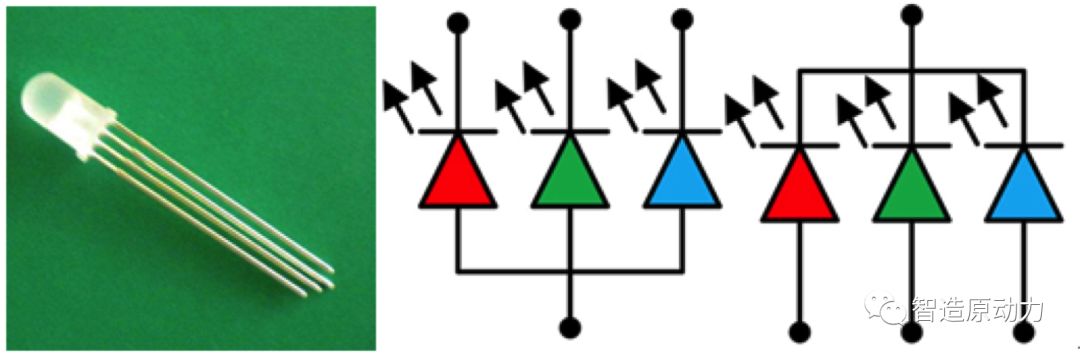
Figure3-2 Full-color LED
Have students ever wondered how full-color LEDs with only red, green, and blue colors can produce more colors? This is related to a property of LEDs: the light intensity increases with rising voltage and decreases with falling voltage. Therefore, by changing the voltage applied to the LED control pins, we can alter the light intensity of the corresponding colors, and by combining different light intensities, we can achieve more colors.
2. PWM Technology
In the previous introduction, we mentioned controlling the light intensity of LEDs by varying the voltage. Here, we will use a technique called PWM (Pulse Width Modulation).
PWM works by modulating the width of a series of pulses to effectively obtain the desired waveform or voltage. Pulse width modulation is an analog control method that adjusts the bias of the transistor gate or base according to the changes in the corresponding load, thereby changing the conduction time of the switching regulator output transistor. This method can keep the output voltage of the power supply constant when working conditions change and is a highly effective technique for controlling analog circuits using digital outputs from microprocessors. In simple terms, if we want to control the speed of a motor or the brightness of an LED light through a program, we need to use PWM technology.
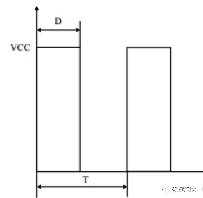
Figure3-3 PWM waveform
Not all pins on the controllers we use support PWM technology. Taking the UNO controller as an example, pins 3, 5, 6, 9, 10, and 11 can achieve this function. By closely observing the Arduino control board, we find that the pins marked with “~” next to the pin numbers can be used for PWM.
[Technology and Practice]
1. Task Description
Create a breathing light. As the name suggests, it is a light that gradually changes from bright to dark under the control of the controller, resembling a breathing light. Next, we will use the full-color LED module to realize a red breathing light.
2. Preparation Work
|
Materials Required |
Quantity |
|
Arduino Uno R3 Main Control Board |
1 piece |
|
IO Expansion Board |
1 piece |
|
Full-color LED Module |
1 piece |
|
Full-color LED Module Connection Wire |
1 piece |
|
USB Download Cable |
1 piece |
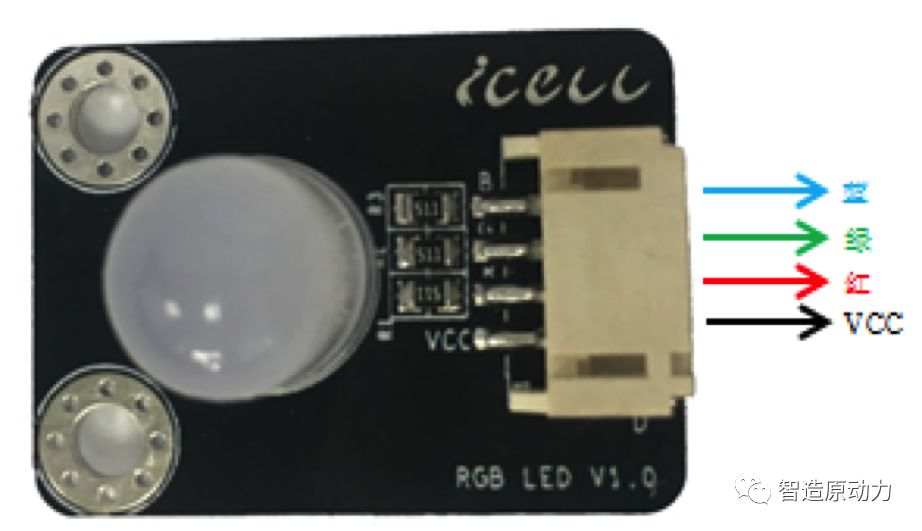
Figure3-4 Full-color LED Module
Before we start our first experiment, let’s first understand the full-color LED module. Figure 3-4 shows a full-color LED module with a common anode full-color LED light. The module interface has four pins, which are, from top to bottom, the blue light control pin, green light control pin, red light control pin, and VCC interface. During use, we need to connect VCC to a high level, then set the other interfaces to low level to light up the corresponding color of LED.
3. Hands-on Production
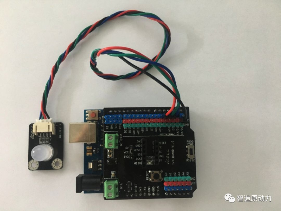
Figure3-5 Full-color LED Module Wiring
As shown in Figure 3-5, students will connect the blue, green, and red wires of the full-color LED module to IO expansion board pins D3, D5, and D6 (pins that can perform PWM), connect the black wire to any VCC, and adjust the jumper cap position on the top IO board so that VCC connects to 5, indicating that VCC is configured to 5V. Then connect the power line and USB line, and we can start programming.
4. Program Design

Figure 3-6 Analog Output Program Module
In the Arduino program, we need to use the analog output control function. Analog output means that the output is not limited to two states but can vary continuously. Recall that in the previous lesson, we used digital ports to control the brightness of the LED light, which only has two states: “0, 1“. The above figure shows the function block for setting the analog pin value, where the number after # represents the pin number (note that the pin number must be one with PWM function), and the last number represents the output voltage value, which ranges from 0~255, corresponding to the voltage of 0V~VCC.
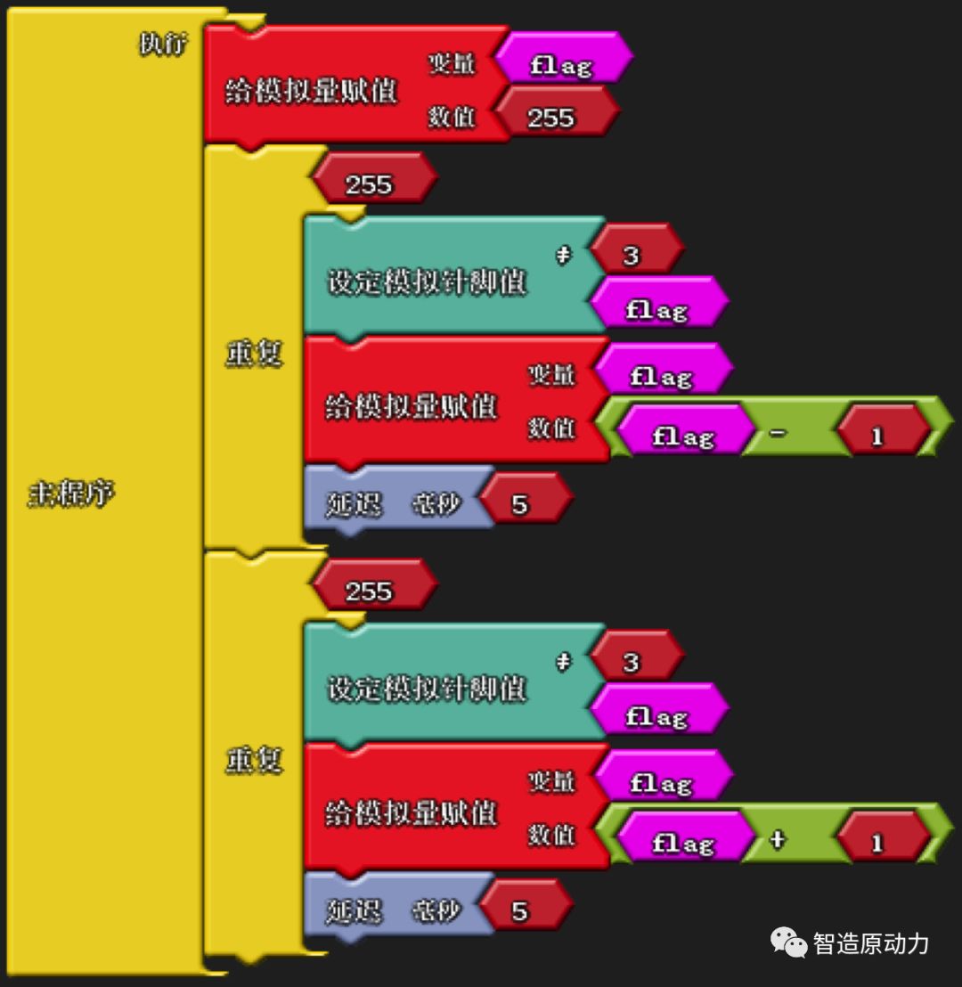
Figure3-7 LED Breathing Light Program
The reference program for the breathing light is shown in Figure 3-7. In the program, we used an analog quantity to assign values to the analog pins. The first loop continuously increases the brightness of the LED, while the second loop continuously decreases the brightness, thus creating the effect of a breathing light.

Figure3-8 Breathing Light Arduino Program
As shown in Figure 3-8, this is the corresponding automatically generated Arduino program. You can see that the function block for setting the analog pin value corresponds to the generated Arduino function called analogWrite(). The first parameter represents the pin number, and students should note that the pin number here must be one with analog output capability. The second parameter is the voltage value for that pin, which can be from 0 to 255, meaning that VCC is divided into 255 parts; the larger the value, the higher the output voltage.
[Tasks and Implementation]
Students, the combination of primary colors can create a rich array of colors. Previously, we programmed the full-color LED module to achieve a breathing light effect. Next, we will create a flashing box that randomly changes colors to further appreciate the unique charm of LED.
1. Task Description
In this task, students need to assemble the flashing box and then program it to make the light color change randomly every 100 milliseconds, just like the beautiful neon lights we see on the streets. Sounds interesting, so let’s get started!
2. Preparation Work
|
Materials Required |
Quantity |
|
Arduino Uno R3 Main Control Board |
1 piece |
|
IO Expansion Board |
1 piece |
|
Full-color LED Module |
1 piece |
|
Full-color LED Module Connection Wire |
1 piece |
|
Flashing Box Assembly Board |
1 set |
|
M3X6 Copper Pillar |
3 pieces |
|
M3X6 Pan Head Screw |
3 pieces |
|
M3 Nut |
3 pieces |
|
Lithium Battery |
1 piece |
|
Power Line |
1 piece |
|
USB Download Cable |
1 piece |
|
Velcro |
1 piece |
3. Hands-on Production
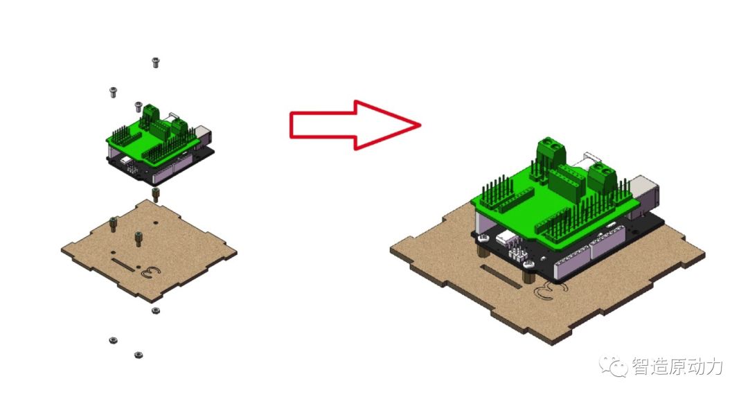
Figure3-9 Flashing Box Installation Step 1
First, students take out the 3 board from the flashing assembly board and, as shown in Figure 3-9, first combine the IO expansion board and Arduino Uno R3, then install the M3X6 pan head screws, M3 nuts, and M3X6 copper pillars at the indicated positions.

Figure3-10 Flashing Box Installation Step 2
Then, everyone takes out the 4 board and the full-color LED module, first installs the full-color LED module on the 4 board using M3X6 pan head screws, and then inserts the 4 board into the designated position on the 3 board.
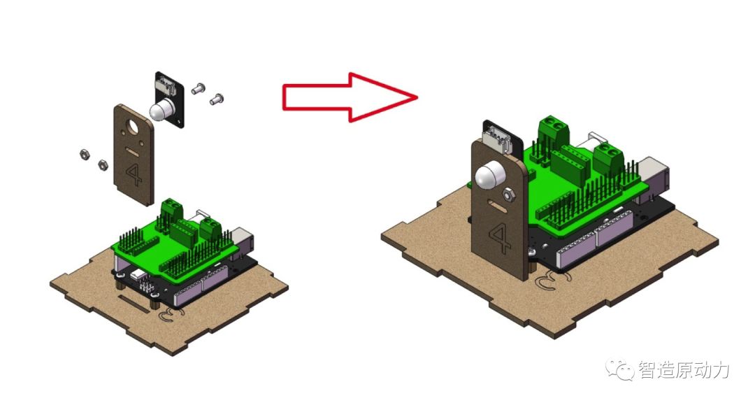
Figure 3-11 Flashing Box Installation Step 3
To make the light emitted from the flashing box cooler, we use double-sided tape to stick the light guide plate to the position on the 1 board.
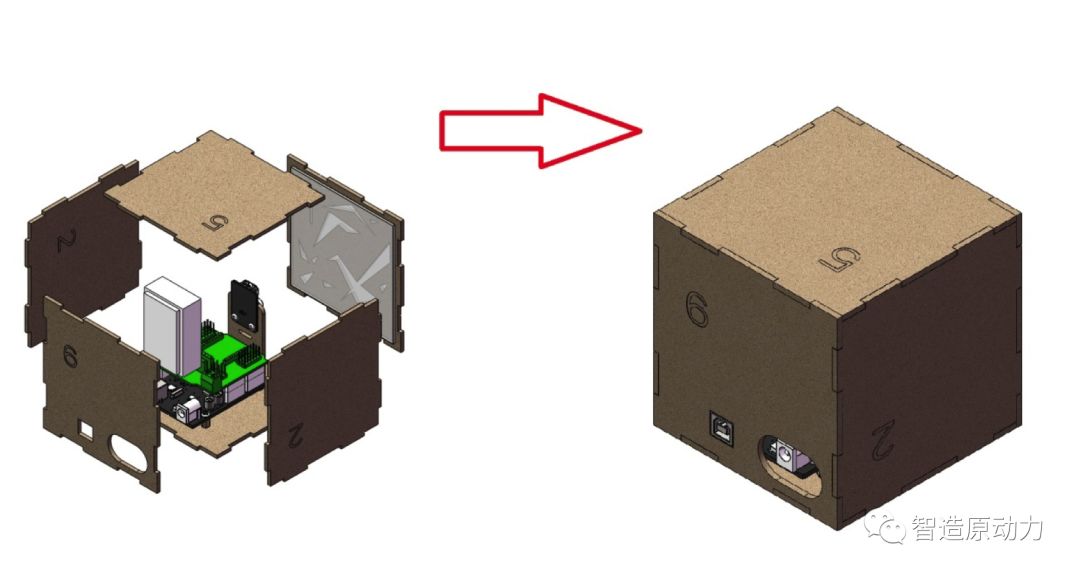
Figure 3-12 Flashing Box Installation Step 4
Finally, everyone sticks the battery to the 6 board with Velcro and assembles all the boards according to the positions indicated in step 4.
5. Program Design
Above, we learned how to control the brightness of the LED light using Arduino and understood the basic principles of primary colors. Now, students can discuss how to generate randomly changing colors.
Everyone must have come to the conclusion that if we apply randomly changing voltages to the three pins controlling red, green, and blue, we can achieve randomly combined colors. Therefore, the key here is how to generate randomly changing voltages. Students should easily think that as long as we can fill in random voltage values in analogWrite, we can generate random voltages.
Have students ever wondered how our eyes perceive colors? The so-called light is also electromagnetic waves, and our eyes recognize colors based on the wavelength of the light they see. Most colors in the visible spectrum are mixed from the primary colors of red, green, and blue in different proportions. When these three lights mix in equal proportions and reach a certain intensity, they present white (white light); when the intensity of all three lights is zero, it is black (darkness). This is the principle of additive color mixing, which is widely used in active light-emitting products such as televisions and monitors.
In ArduBlock, there is a random module in the practical command options for generating random numbers, as shown in the figure below. The number in the red box of the module indicates the range of random number generation. Since the voltage value for analogWrite is 0 to 255, we fill in 255 here, indicating that random numbers are generated between 0 and 255.

Figure3-13 Loop Program Module
Finally, the reference program for the flashing box is shown in Figure 3-14.
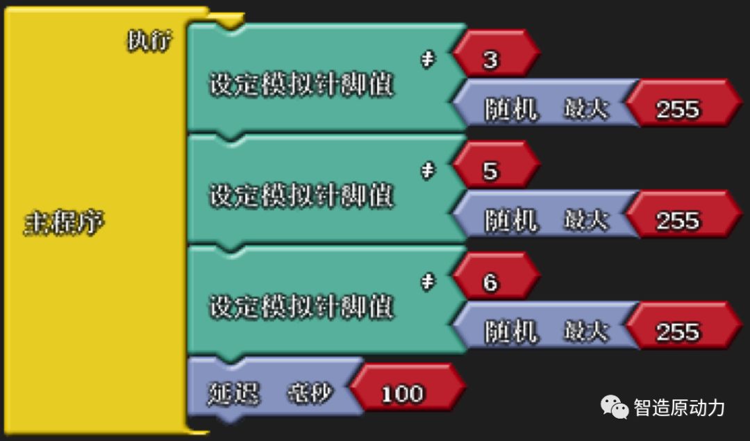
Figure3-14 Traffic Light Simulation Program
The program is simple: it assigns a random voltage value to the three pins controlling the full-color LED every 100 milliseconds, and when we download the program, we can see the cool performance of the flashing box.

Figure3-15 Flashing Arduino Program
Above is the corresponding Arduino program. Students may notice that the random data module in ArduBlock corresponds to the Arduino function called random, which is quite intuitive in English. Additionally, attentive students will discover a function called randomSeed, where Seed means seed. What does this mean? In fact, generating random numbers requires an initial number, and then through calculations, we obtain random numbers at different times. This function is used to obtain that initial number.
5. Results Display
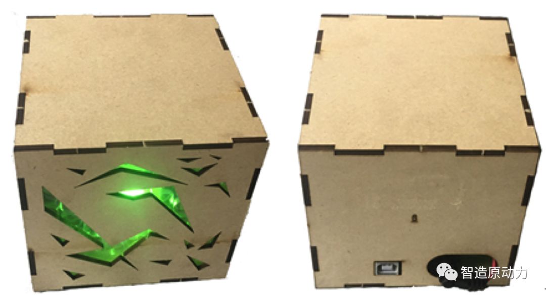
Figure 3-16 Flashing Box Results Display
[Expansion and Reflection]
In the examples above, we see that primary colors combine to create various colors. But how can we decompose these colors back into their primary colors? On one hand, it can be derived through rules; on the other hand, previous efforts have established a complete table, allowing us to know the required primary colors by consulting the table. Students are encouraged to try creating their own primary color table and see if they can combine to create orange or yellow.
In fact, the primary colors of red, green, and blue mentioned earlier are also known as the additive primary colors, which refer to the three primary colors contained in self-luminous objects, such as our LEDs and the sun, which emit light on their own. However, colors that do not emit light and require illumination to be seen follow a different system called subtractive primary colors. This system’s primary colors are magenta (equivalent to rose red), cyan (a deeper sky blue), and yellow (equivalent to lemon yellow). Additionally, because subtractive primary colors cannot be mixed to form pure black, black is also added to form the color system.