Abstract: This article introduces the design of a high-precision altitude acquisition system based on DSP and the BMP085 digital barometric pressure sensor for drones, along with the testing and analysis of the actual operational data of the system, achieving altitude measurement and transmission. The focus is on the design and implementation of the software and hardware at the system acquisition end, explaining the design requirements for both software and hardware. This system features low power consumption, simple structure, high precision, strong anti-interference capability, and the ability to reduce the impact of environmental factors. The measurement system uses the Kalman filter algorithm to correct the measurement data for more accurate calculation of relative altitude.
Autonomous flying drones represent a cutting-edge research topic across multiple disciplines. Drones operate without human control in the cabin and rely on various electronic devices to automatically complete various flight maneuvers during flight. Altitude information, as a flight parameter for drones, is an important indicator for ensuring the normal operation of the drone’s flight control system and maintaining safe and stable flight. This article focuses on the BMP085 pressure sensor and employs the Kalman filter algorithm to construct a more precise altitude acquisition system using the TMS320F2812 DSP.
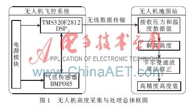
1 System Working Principle and Hardware Structure The hardware part of the DSP-based drone altitude acquisition system mainly consists of three parts: pressure and temperature acquisition, data processing, and data transmission. This system uses a pressure and temperature sensor to collect the pressure and temperature values of the drone, which are sent to the drone’s processor. Wireless transmission is used to send data to the ground control center, where the relative altitude value is calculated through formulas. The Kalman filter algorithm is then applied to correct the data for a more accurate altitude value, facilitating ground station personnel in controlling the drone to operate at a safe and reliable flight altitude.
1.1 Overall Structure of the System The overall structure of the DSP-based drone altitude acquisition system is shown in Figure 1. The hardware part of the system consists of the BMP085 digital barometric pressure sensor, TMS320F2812 DSP, wireless transmission module, power module, and other peripheral circuits. The TMS320F2812 controller connects to the BMP085 pressure sensor via I/O ports simulating an I2C bus. The BMP085 sensor continuously obtains the pressure and temperature values at the measurement point and transmits them to the controller for processing through the I/O port. The pressure and temperature data are transmitted in real-time to the drone’s ground station via the drone’s wireless transmission module. After receiving the data, the ground station calculates the corresponding altitude value based on the pressure-altitude conversion relationship, compensates for the altitude value, and uses the Kalman filter algorithm for data correction. The analyzed data is then stored, and control commands are sent to the flight control center via the uplink data chain to adjust the drone’s attitude, thereby controlling its altitude for a smoother flight.
1.2 Hardware Selection of the System The TMS320F2812 digital signal processor is a latest 32-bit fixed-point DSP controller launched by TI, and is one of the most advanced processors in the control field. Its frequency reaches up to 150 MHz, greatly enhancing the control precision and chip processing capability of the control system; the data processing bit has also increased from 16-bit fixed-point to 32-bit fixed-point. The standout feature is its EVA, EVB event manager and supporting 12-bit 16-channel A/D data acquisition, supporting JTAG boundary scan interfaces; it features an 8 KB internal ROM and 128 KB internal Flash memory, three 32-bit CPU timers; serial communication peripherals mainly include one SPI serial interface, two SCI serial interfaces, and enhanced controller area network communication interface Ecan2.0B; it has 56 configurable general-purpose I/O pins; it supports low-power and energy-saving modes; the external I/O port voltage is 3.3 V, and the core voltage is 1.8 V, with Flash programming voltage at 3.3 V; available in 179-pin BGA and 176-pin LQFP packages.
To meet the system’s overload resistance requirements, the BMP085 pressure sensor based on MEMS technology from Bosch is used. The BMP085 features a robust 8-pin ceramic leadless chip carrier (LCC) ultra-thin package, with a pressure measurement range of 30 kPa to 110 kPa (equivalent to -500 m to 9,000 m), and an absolute accuracy of up to 0.03 hPa (0.25 m). The temperature measurement range is from -40°C to +85°C. The BMP085 transmits uncompensated temperature and pressure values, and compensated temperature and pressure values can be obtained using standard data stored in the BMP085’s EEPROM. The EEPROM stores 176 bits of individual standard data, which is used for temperature and pressure compensation, with 176 bits divided into 11 words, each 16 bits, totaling 11 calibration coefficients, each device module has its unique calibration coefficients.
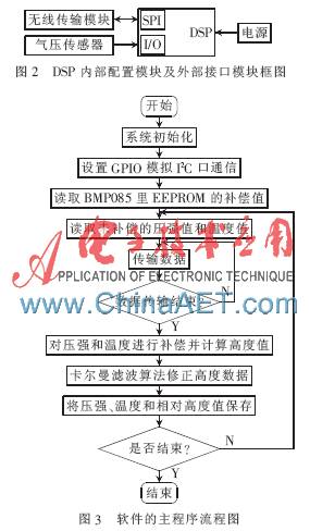
1.3 Internal Framework of the DSP System Since the pressure sensor data is transmitted to the DSP via the I2C bus, and the TMS320F2812 lacks an I2C bus interface, the I/O ports of the TMS320F2812 are used to simulate the I2C bus. The wireless transceiver module sends data to the drone’s ground station via SPI, thus requiring both SPI and I/O in the system to receive and send data for a complete system design. The DSP internal structure includes these two parts, and it is only necessary to call these modules and configure their parameters to facilitate data transmission with external interface modules, as shown in Figure 2.
2 Software Design of the System The software design program for the measurement system is based on Keil uVision4 and written in C language. The program design approach is top-down, employing a modular design scheme, which mainly includes three subprogram modules: system initialization, I/O port simulating I2C communication, and Kalman filter algorithm for data correction. The main program operates in a loop, as illustrated in the system workflow diagram in Figure 3.
2.1 I/O Port Simulating I2C Communication I/O port simulating I2C communication is primarily used for communication between TMS320F2812 and BMP085. After setting up the I/O port simulating I2C communication, the controller reads the 11 compensation coefficients from the BMP085’s EEPROM in advance, facilitating subsequent temperature compensation calculations. The DSP sends a start signal to the BMP085 sensor to initiate pressure and temperature measurements. Upon receiving the start signal from the DSP, the BMP085 begins measuring the current pressure and temperature. After a conversion time of 4.5 ms, the DSP uses the I2C interface to read the pressure and temperature measured by the BMP085 sensor and performs temperature compensation based on the obtained compensation coefficients.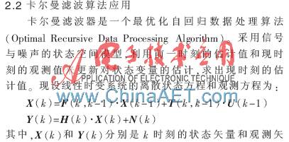

This drone was completed during the summer of 2011 and underwent remote control test flights and adjustments, with a maximum load of 2.5 kg and flight duration sufficient for general cruising tasks. The cabin space is quite ample, with an installable volume of 7 cm×8 cm×9 cm; considering this point, the hardware circuit board is designed in a plug-in format.
The BMP085 digital pressure sensor provides a reference formula for pressure-altitude conversion. Using this formula in conjunction with the pressure values collected by the sensor can yield good altitude measurements, which become more precise after applying the Kalman filter. The pressure-altitude formula is: Altitude=44 330[1-(P-P0)(1/5.255)], where Altitude is the altitude value in meters, P0 is the standard atmospheric pressure, and P is the atmospheric pressure at a given altitude. The overall testing results are shown in Table 1, comparing the altitude measurement results of this system with theoretical values based on altitude measurements. Due to limited experimental conditions, the altitude range is 0 to 500 m.
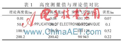
From Table 1, it can be seen that the maximum error value calculated by the system within the measurement range is 0.52 m, with the system error generally being less than 1 m. The errors in the pressure altitude acquisition system are mainly caused by the sensor’s inherent errors, circuit errors, and calculation errors. The system ensures high precision in measurement results through sensor calibration, temperature compensation, software filtering, and calculation of altitude formulas, thus meeting the requirements for altitude measurement.
The high-precision altitude acquisition testing system designed using the BMP085 atmospheric pressure sensor and TMS320F2812 DSP, through simple circuitry and effective software filtering algorithms, demonstrates good stability and high precision, suitable for multifunctional needs such as high accuracy, small size, and portability, with a broad application prospect in practical life.
References[1] Wang Xuan, Li Xiaomin. Design of a High-Precision Small Drone Pressure Altitude Measurement System[J]. Measurement and Control Technology, 2012, 31(2): 12-15.[2] Liang Shengzhan, Guo Xuemei, Yu Xiaotian. Research and Implementation of Altitude Measurement Based on BMP085 Pressure Sensor and BP Algorithm[J]. Journal of Sensor Technology, 2013(5): 654-659.[3] Jiang Leping. Research on the Flight Control System of Solar Airship Based on DSP[D]. Nanchang: Graduate School of Nanchang Hangkong University, 2012.[4] Wang Juncai, Wang Fuping, Hou Ruifeng, et al. Design of a Portable Altitude Measurement System Based on BMP085[J]. Sensors and Microsystems, 2011, 30(12): 123-125.[5] Wang Qi, Jiang Leping. Design of an Airship Internal Temperature Acquisition System Based on PSoC[J]. Electronic Technology Application, 2012, 38(1): 41-43.[6] Jing Xi. Basics of Kalman Filter and Its Applications[M]. Beijing: National Defense Industry Press, 1973.