In the global carbon neutrality framework, DAC (Direct Air Capture) is transitioning from a laboratory concept to a fundamental energy infrastructure. Meanwhile, electrochemical CO₂ conversion (CO₂ Electrolysis) is becoming an important pathway for green synthetic fuels, renewable chemicals, and negative carbon new materials.
As DAC and CO₂ electrolysis, two originally independent technological systems, begin to merge, a critical question arises:
Which route between liquid phase DAC and solid phase DAC is more suitable as the front end for electrochemical CO₂ conversion?
Which route better supports the systematic development of future distributed PtX (Power-to-X) plants?
This article provides an in-depth analysis of the two types of DAC technologies from four dimensions: global engineering practices, material mechanisms, cost trends, and system coupling, and offers technological judgments for the next decade.
⸻01|Underlying Mechanisms of Two Routes: Chemical Forms Determine Engineering Fate The two routes of DAC—solid phase and liquid phase—are essentially two completely different adsorption mechanisms, and thus represent two entirely different engineering worlds.⸻① Solid Phase DAC: Solid Surface Chemical Adsorption + Medium-High Temperature or Vacuum Desorption The core of solid phase DAC is to immobilize amine, hydroxyl, or basic functional groups on porous materials (such as zeolites, silica, carbon materials, MOFs, etc.), utilizing the selective adsorption of CO₂ on the solid surface to achieve enrichment.Adsorption Phase: • Room temperature or low temperature • Gas-solid interface contactDesorption Phase: • Medium temperature (80–120°C) or high temperature (400–900°C) • Or strong vacuum (VSA) • Or humidity switching The process of solid phase DAC seems simple, but it has inherent engineering characteristics: • Adsorption-desorption is periodic • Gas can only be output intermittently • Huge temperature span (25–900°C) • Energy consumption highly depends on external heat sources Solid phase DAC resembles a “adsorption bed + regeneration bed” cycling system, leaning towards large independent carbon removal devices.⸻② Liquid Phase DAC: Molecular Solution Absorption + Low Temperature Analysis + Continuous Cycle Liquid phase DAC uses alkaline solutions or amine absorbents, with mechanisms similar to wet decarbonization:Absorption: • 20–40°C room temperature • CO₂ + absorbent molecules react • Fast, controllable, stableRich Liquid-Poor Liquid Cycle: This is the greatest engineering advantage of the liquid phase system: It is a continuous process of chemical reaction + fluid circulation.Analysis: • 60–120°C • Temperature range overlaps with the electrolyzer’s thermal zone • CO₂ is released in a stable, continuous manner Therefore, liquid phase DAC is essentially a “continuous reactor + low-temperature desorption tower,” naturally fitting continuous flow processes.⸻Underlying Determines Upper Level: Solid phase DAC = Periodic Equipment Liquid phase DAC = Continuous Process This lays the key difference for the subsequent question of “suitability for electrochemical CO₂ conversion.”⸻02|Looking at DAC from the Perspective of Electrochemical CO₂ Conversion: Gas Supply Capability is More Critical than Capture Rate Many discussions about DAC focus solely on “capture rate, adsorption speed, material stability,” but for electrochemical CO₂RR, what truly matters is: Can DAC provide “continuous, stable, mild” CO₂ inflow? Can it form system coupling with the electrolyzer, rather than being two isolated devices? The following four points are the most valued “front-end standards” for CO₂ electrolysis systems.⸻① Continuity (Continuous Flow) is Absolutely Core Electrolyzing CO₂ is not a device that can react with a single breath; it is a continuous production unit that highly depends on stable fluid supply. If CO₂ supply experiences: • Fluctuating gas flow • Pressure fluctuations • Intermittent waveforms (on–off) • Unstable moisture content It will immediately cause: • Catalyst gas-liquid interface collapse • Membrane material oversaturation • Current density cannot be maintained • Product distribution changes • Irreversible decay Solid phase DAC is inherently “periodic,” while liquid phase DAC is inherently “continuous.” Just this point alone is enough to determine which route is more suitable for CO₂RR.⸻② Temperature Must Be Maintained in the 30–70°C Range and Stable Electrochemical CO₂RR has strict temperature control requirements: • Below 25°C, reaction kinetics decline • Above 70°C, membranes will lose water or mechanically degrade • ΔT (temperature difference) exceeding ±5°C will cause significant current fluctuations Solid phase DAC desorption outlets often range from 80–900°C, requiring substantial cooling to approach the temperature range needed for the electrolyzer. In contrast, the desorption temperature of liquid phase DAC—60–120°C—almost matches that of the electrolyzer. This means: Liquid phase DAC can naturally match the electrolyzer and even reuse residual heat from the electrolyzer. (This is fundamental for subsequent system efficiency optimization.)⸻③ Pressure, Humidity, and Water Content Must Be Controllable PEM/AEM CO₂ electrolysis is extremely sensitive to humidity: • Overly humid → Catalyst layer flooding, GDE submersion • Overly dry → Membrane dehydration, ion conductivity decline • Pressure fluctuations → Gas-liquid interface disruption Solid phase DAC’s gas output relies on the condition of the adsorption bed, making water content difficult to stabilize and control. Liquid phase DAC’s CO₂ output, after gas-liquid separation, is naturally dried, easily stabilized, and easy to adjust humidity.⸻④ Thermal Coupling with the Electrolysis Process is the Key Path for Future Cost Reduction Both CO₂ electrolysis and water electrolysis generate a large amount of heat at 50–80°C, while the liquid phase DAC’s desorption system is precisely located within this temperature range. It can achieve: • Desorption tower utilizing residual heat from the electrolyzer • Cooling water from the electrolyzer as preheating for DAC • After thermal coupling, total system energy consumption decreases by 15–30% Solid phase DAC cannot achieve this because the required heat source temperature is entirely different.⸻03|Liquid Phase vs Solid Phase DAC: Systematic Differences in Four Directions The real comparison is not which material is more advanced, but which is more suitable for “system integration.” Below are the key differences from points 1 to 4.⸻① CO₂ Output Temperature and Electrolyzer CompatibilityTechnical Route CO₂ Output Temperature Electrolyzer CompatibilitySolid Phase DAC 80–900°C Not compatible, requires complex coolingLiquid Phase DAC 60–120°C Fully compatible Even if solid phase DAC has high desorption efficiency, the cooling costs are enormous. Liquid phase DAC naturally operates within the electrolyzer’s working range, with almost zero matching costs.⸻② Continuity vs Periodicity: The Most Decisive Dimension for System Fate The gas source output of solid phase DAC is typically: Adsorption → Regeneration → Cooling → Switching → Re-adsorption (Intermittent, periodic) Liquid phase DAC, on the other hand, is: Absorption Tower → Rich Liquid → Analysis Tower → CO₂ Release → Poor Liquid → Absorption Tower (Continuous, steady state) Continuity is an absolute prerequisite for electrochemical CO₂RR. Any discontinuity will directly lead to system decay.⸻③ Does Thermal Management and Energy Consumption Structure Support Coupling? Solid Phase DAC: • Requires high-temperature heat sources • Requires independent heating systems • Regeneration process cannot share heat with electrolysis • Energy consumption cannot be split or shared • System efficiency cannot be optimized as a whole Liquid Phase DAC: • Desorption temperature range overlaps with the electrolyzer • Can reuse residual heat from the stack • Heat pumps and heat exchangers can be designed together • Achieve “optimal design for overall energy efficiency” From a systems engineering perspective, liquid phase DAC is far superior.⸻④ Does it Have the Potential for “Electro-Driven Regeneration” (Electro-DAC)? This is a core trend for the future. Solid Phase DAC: • Strong bonds formed between immobilized amine and CO₂ • High difficulty for electro-driven desorption • Cannot directly participate in electrochemical processes Liquid Phase DAC: • Rich liquid can undergo electrochemical desorption (ED, ESR) • Rich liquid can directly participate in cathodic reactions • Capture and conversion can gradually merge Liquid phase DAC possesses the true potential for “DAC-electrolysis integration.”⸻04|Why Liquid Phase DAC Becomes the Mainstream Front-End Route for Global PtX Plants? Liquid phase DAC has three characteristics that resonate naturally with PtX systems:⸻① Modularizable: 20ft / 40ft Container Solutions Solid phase DAC has large tower bodies, heavy vacuum systems, and cannot be easily downsized. The absorption tower, regeneration tower, pump system, and heat exchanger of liquid phase DAC are highly consistent with the engineering forms of PEM/AEM electrolyzers. Therefore, they can share: • Framework • Control systems • Pipelines • Heat exchange networks Forming modular PtX production units.⸻② Deployable in Remote Areas (Photovoltaic Fields + Coastal + Desert) The temperature range of liquid phase DAC can directly utilize: • Photovoltaic waste heat • Electrolyzer waste heat • Seawater cooling • Low-temperature heat pumps Suitable for deployment in sunny regions such as Southern Europe, the Middle East, and Australia.⸻③ Directly Connectable to CO₂ Electrolysis, Methanol Synthesis, Green Methane Systems Liquid phase DAC can provide: • Stable flow • Stable pressure • Low water content • CO₂ close to process temperature Therefore, it can seamlessly connect to: • CO₂ → CO • CO₂ → HCOOH • CO₂ + H₂ → CH₃OH • CO₂ + H₂ → CH₄ • CO₂ → Syngas This is also the mainstream technical combination for global DAC+PtX projects.⸻05|System Energy Consumption, Operating Costs, and Engineering Boundaries: The “true engineering face” of liquid phase DAC vs the structural limitations of solid phase DAC The most easily underestimated aspect from laboratory to engineering is energy consumption structure. The energy consumption of DAC mainly comes from three stages: 1. Air propulsion (large airflow fans) 2. Regeneration of adsorbents or absorbents 3. Gas treatment (compression, cooling, drying, etc.) Regardless of the route, fans are the absolute main force—after all, CO₂ in the air is only 420 ppm, requiring processing of thousands of cubic meters of air to obtain sufficient CO₂. However, the real gap is in regeneration energy consumption and thermal management capability.⸻(1) Solid Phase DAC: Structural Energy Consumption Bottleneck Due to High Thermal Demand Solid phase DAC’s adsorbents typically form strong chemical bonds with CO₂, thus regeneration requires: • High temperature • Vacuum • Or humidity switching Its energy consumption structure presents a typical “high irreversible loss”:Energy Consumption Stage Solid Phase DAC Energy Consumption Typical ValuesFan 200–400 kWh/tCO₂Heating Desorption 3–7 GJ/tCO₂Vacuum System 0.5–1.0 GJ/tCO₂Total Energy Consumption 5–9 GJ/tCO₂ The key is— The thermal demand temperature of solid phase DAC is too high, making it difficult to reuse waste heat from electrochemical systems or new energy devices. This forms a natural shortcoming: • Independent heat source → High operating costs • Independent cooling system → High CAPEX • Cannot share energy links with electrolysis, PtX, etc. • Difficult to integrate into low-cost modular systems Solid phase DAC is more suitable for: • Independent carbon removal facilities • Large-scale projects with annual operation >8000 hours • Environments with cheap industrial waste heat But it is not suitable as the front end of electrochemical CO₂ reactors.⸻(2) Liquid Phase DAC: Low-Temperature Analysis Supports “Thermal-Electric Integration” Optimization The desorption temperature range of liquid phase DAC is:60–120°C Just right within: • PEM/AEM electrolyzer waste heat range (50–80°C) • Photovoltaic inverter waste heat range • Hydrogen cycle heating range • Low-temperature heat pump usable range Its typical energy consumption structure is as follows:Energy Consumption Stage Liquid Phase DAC Energy Consumption Typical ValuesFan 200–400 kWh/tCO₂Low-Temperature Analysis Heat Source 0.8–1.6 GJ/tCO₂Circulation Pump/Heat Exchange 10–30 kWh/tCO₂Total Energy Consumption 1.2–2.0 GJ/tCO₂ Compared to solid phase DAC: • Energy consumption decreases by 60–80% • Heat sources can be reused → System efficiency significantly improves • Suitable for renewable energy scenarios (wind-solar hydrogen + DAC) • Desorption temperature range is more tolerant, and control systems are simpler More importantly: The thermal coupling capability of liquid phase DAC allows it to become the “thermal management center” of PtX plants.⸻(3) Engineering Boundaries: Why is Liquid Phase DAC Easier to Scale? Solid Phase DAC: • Large arrays of adsorption beds • Extensive heating-cooling cycles • Complex vacuum equipment and sealing structures • High simulation difficulty, unstable cycles Liquid Phase DAC: • Process flow is similar to traditional decarbonization (nearly 50 years of mature engineering systems) • Can easily achieve hundreds of Nm³/h continuous cycles • High equipment maturity (towers, heat exchangers, pumps) • Consistent with the module forms of electrolyzers and PtX processes • Can be made into replicable modules of 5–50 tCO₂/day In the future, DAC will modularize like electrolysis, and liquid phase DAC clearly has an advantage in engineering adaptability.⸻06|Key Coupling Points for Adapting to Electrochemical CO₂ Conversion: How Liquid Phase DAC Forms Real “System-Level Resonance” with Electrolysis? Liquid phase DAC is considered the most suitable route for CO₂RR not only because of its “continuous, low temperature” but also because it can form genuine link synergy with the electrochemical system. Below are the three coupling points most focused on by the industry:⸻(1) CO₂ Purity, Humidity, and Pressure are Easier to Control The CO₂ output characteristics of liquid phase DAC: • Temperature at 40–80°C • Pressure easily stabilized at 1–2 bar • After gas-liquid separation, can maintain < 100 ppm H₂O • Free of solid phase dust or adsorbent particles • Water content can be controlled through simple condensation/drying Almost completely matches the conditions required for electrolysis CO₂RR. In contrast: The CO₂ from solid phase DAC: • Water content fluctuates with the material’s adsorption state • High temperature, high humidity, must be dried • Unstable pressure • Requires strict gas regulation systems The “controllability of gas source quality” of liquid phase DAC greatly reduces the complexity of the electrolysis process.⸻(2) Rich Liquid (HCO₃⁻/CO₃²⁻) Can Be Directly Used for Electrochemical CO₂ Conversion This is the most promising frontier direction. Rapidly developing systems internationally include: • Rich liquid electrolysis generating CO (HCO₃⁻→CO) • Electrodialysis promoting CO₂ desorption + immediate reaction • Capture liquid as part of the electrolyte • In-situ conversion of CO₂ in rich liquid environments Example reaction pathways:
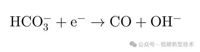
This means: DAC → Electrolysis CO₂ no longer needs the “gas CO₂” stage, transforming into “liquid rich liquid → electrochemical products.” Solid phase DAC cannot achieve this at all.⸻(3) Thermal Management, Energy Consumption Management, and Power Management Can Be Unified in Design Liquid phase DAC and electrolysis CO₂ can share: • Thermal coupling network • Water management system • DI water and distillation recovery chain • Compressor system • Energy scheduling system • Control system (PLC/DCS) Forming a truly systematic engineering of “capture–electrolysis–synthesis” full-link system, which is the modular engineering unit that your EPC is currently laying out.⸻07|Future Trends: Why Liquid Phase DAC Will Become the Mainstream Choice for PtX Plants? The future competition of DAC will no longer be a “capture efficiency competition” but a competition of “system coupling capability.” In the next 10 years of PtX projects (green methanol, green methane, green ammonia, green aviation fuel, CO₂→CO), the plant forms will show a clear trend:⸻(1) From Large Independent Facilities → Modular PtX Units Solid phase DAC: • More suitable for ultra-large unified deployment • Difficult to flexibly distribute according to scenarios Liquid phase DAC: • Suitable for 3–30 tCO₂/day • Can build multi-point gas supply according to scenarios • Can be integrated with electrolyzers and hydrogen systems, meaning a PtX plant can be built like “stacking blocks.”⸻(2) From Fossil Energy Parks → Renewable Energy Nodes Liquid phase DAC’s energy structure matches highly with wind-solar hydrogen: • Utilizing photovoltaic waste heat • Utilizing electrolyzer waste heat • Smaller distributed systems are more economical • More suitable for deployment in remote areas, desert islands Your EPC containerization scheme is at the center of this trend.⸻(3) From “Gas CO₂ Input” → “Rich Liquid Input for Electrochemical Reaction Chain” Traditional process: Air → DAC → CO₂ gas → Electrolyzer Future process: Air → Liquid phase DAC → Rich liquid → Electrolyzer (in-situ conversion) Shorter link, lower energy consumption, simpler devices.⸻(4) From Capture Equipment → System Reactor The role of liquid phase DAC will upgrade from “CO₂ capturing device” to “the front-end reactor of the CO₂ electrochemical system.” This means it is no longer a carbon removal device but the first unit of PtX.
⸻
08|EPC’s Perspective
EPC’s view: Future DAC will not be an independent device but the “front-end reactor” of electrolysis CO₂ plants. Liquid phase DAC, due to its low temperature, continuous flow, and electrochemical regeneration characteristics, will become the most natural, cost-effective, and system-efficient entry point for electrochemical CO₂ conversion.
This is a key trend in the reconstruction of future green fuel plants.
Conclusion|The True Competition of DAC Lies Not in Capture Rate, but in System Coupling Depth
The next stage of competitiveness for global PtX, negative carbon fuels, and renewable chemicals lies not in single-point materials, but in:
-
System Coupling Capability
-
Thermal Efficiency of Energy Chain
-
Modular Deployment Capability
-
Continuity of Gas Supply—Electrolysis—Synthesis
Liquid phase DAC is strategically positioned in this new system:
It can both capture CO₂ and deeply integrate with electrochemical processes, becoming an important entry point for future negative carbon energy systems.
This will be one of the most noteworthy trends in distributed energy over the next decade.

 Electro Power Cell Energy Technology (Shanghai) Co., Ltd.
Electro Power Cell Energy Technology (Shanghai) Co., Ltd.🌐 Official Website: www.electropowercell.net📧 Email: [email protected]📱 WhatsApp: +86 136 8167 1402
We are committed to building a system platform for “hydrogen energy—carbon capture—green fuel,” enabling energy to transition from physical transformation to logical construction, promoting the full-chain replicability from “electrolysis to hydrogen” to “electrolysis to liquid.”