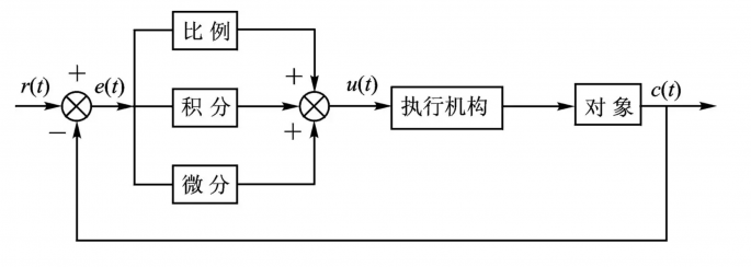
Overview of the Principle
A stepper motor is a motor driven by digital signals, one of its main advantages being its excellent open-loop control capability, where the control system does not require sensors and corresponding circuits to feedback motor information.
Under conditions where the load is not overloaded and the pulse frequency is appropriate, the number of pulses received by the stepper motor and the angular displacement of the rotor are strictly proportional.
Although stepper motors can perform well in open-loop control, in some open-loop systems, the stepper motor may lose steps, overshoot, or even stall during rapid start-stop or sudden load changes due to its own performance and system mechanical structure. The controller cannot know and correct these phenomena, which may lead to serious consequences in systems with high precision requirements.
By adding sensor feedback to form a closed-loop system, it can detect phenomena such as loss of steps and correct deviations in a timely manner.
There are many closed-loop control schemes for stepper motors, which can fully control the torque and position of the stepper motor, improve the torque frequency characteristics of the stepper motor, reduce heating and average power consumption, and enhance motor operating efficiency.
Some control terms we often hear, such as speed loop, position loop, and current loop, can also be applied to closed-loop control of stepper motors, and of course, these terms are similarly applicable to other motor closed-loop systems.
Below we will use the speed of the stepper motor as the controlled quantity (i.e., speed loop), using a rotary encoder as the feedback sensor, and the PID algorithm for the closed-loop control system.
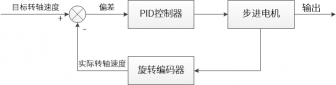
Speed Closed-Loop Control – Incremental PID
Next, we can create:
pid.h and pid.c files to store the relevant programs for the PID controller.
stepper_ctrl.c and stepper_ctrl.h files to store the stepper motor speed loop control program and related macro definitions.
Steps
• Timer IO configuration
• Initialization of relevant peripherals for stepper motor and encoder
• Implementation of speed closed-loop control
• PID parameter tuning
Testing Environment
STM32F103VE version or above, external high-speed crystal oscillator: 8MHz, RTC crystal oscillator: 32.768KHz.
All bus operating clocks: system clock = SYCCLK = AHB = 72MHz, APB2 = 72MHz, APB1 = 36MHz
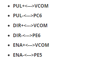
Stepper Motor Driver Interface
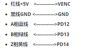
Wiring of the Encoder and Stepper Motor
Code Analysis
The first step is to check the stepper_ctrl.h file, which initializes the GPIO for the stepper motor, etc.
#ifndef __STEP_MOTOR_INIT_H#define __STEP_MOTOR_INIT_H#include "stm32f1xx_hal.h"//Motor Direction #define MOTOR_DIR_PIN GPIO_PIN_6 #define MOTOR_DIR_GPIO_PORT GPIOE #define MOTOR_DIR_GPIO_CLK_ENABLE() __HAL_RCC_GPIOE_CLK_ENABLE()//Motor Enable #define MOTOR_EN_PIN GPIO_PIN_5#define MOTOR_EN_GPIO_PORT GPIOE #define MOTOR_EN_GPIO_CLK_ENABLE() __HAL_RCC_GPIOE_CLK_ENABLE()//Motor Pulse#define MOTOR_PUL_IRQn TIM8_CC_IRQn#define MOTOR_PUL_IRQHandler TIM8_CC_IRQHandler#define MOTOR_PUL_TIM TIM8#define MOTOR_PUL_CLK_ENABLE() __HAL_RCC_TIM8_CLK_ENABLE()#define MOTOR_PUL_PORT GPIOC#define MOTOR_PUL_PIN GPIO_PIN_6#define MOTOR_PUL_GPIO_CLK_ENABLE() __HAL_RCC_GPIOC_CLK_ENABLE()#define MOTOR_PUL_CHANNEL_x TIM_CHANNEL_1#define MOTOR_TIM_IT_CCx TIM_IT_CC1#define MOTOR_TIM_FLAG_CCx TIM_FLAG_CC1/*Frequency Related Parameters*///The actual timer clock frequency is: 72MHz/TIM_PRESCALER//The specific required frequency can be calculated#define TIM_PRESCALER 16 /*Note: For F103 routine testing, increasing the prescaler is beneficial for stabilizing the position loop*/ //Define the timer period, set the output compare mode period to 0xFFFF#define TIM_PERIOD 0xFFFF/************************************************************/#define HIGH GPIO_PIN_SET //High Level#define LOW GPIO_PIN_RESET //Low Level#define ON LOW //On#define OFF HIGH //Off#define CW HIGH //Clockwise#define CCW LOW //Counterclockwise//Control Enable Pin/* Macro with parameters can be used like inline functions */#define MOTOR_EN(x) HAL_GPIO_WritePin(MOTOR_EN_GPIO_PORT,MOTOR_EN_PIN,x)#define MOTOR_PUL(x) HAL_GPIO_WritePin(MOTOR_PUL_GPIO_PORT,MOTOR_PUL_PIN,x)#define MOTOR_DIR(x) HAL_GPIO_WritePin(MOTOR_DIR_GPIO_PORT,MOTOR_DIR_PIN,x) #define MOTOR_EN_TOGGLE HAL_GPIO_TogglePin(MOTOR_EN_GPIO_PORT,MOTOR_EN_PIN)#define MOTOR_PUL_TOGGLE HAL_GPIO_TogglePin(MOTOR_PUL_PORT,MOTOR_PUL_PIN)extern TIM_HandleTypeDef TIM_StepperHandle;extern void stepper_Init(void);#endif /* __STEP_MOTOR_INIT_H */stepper_ctrl.h includes the step angle of the stepper motor, the subdivision number of the driver, and the target speed used for PID control.
The parameters of the stepper motor itself and the parameters needed for closed-loop control include the step angle of the stepper motor, the subdivision number of the driver, and the target speed used for PID control.
Among them, the macro PULSE_RATIO is the ratio of the number of pulses per revolution of the stepper motor to the number of pulses per revolution of the encoder, because in the entire speed closed-loop control system, the feedback and the PID calculated values are all based on the encoder’s pulse count.
#ifndef __STEP_MOTOR_CTRL_H#define __STEP_MOTOR_CTRL_H#include "stepper_init.h"#include "encoder.h"/*Macro Definitions*/#define T1_FREQ (SystemCoreClock/TIM_PRESCALER) // Frequency ft value/*Motor Single Circle Parameters*/#define STEP_ANGLE 1.8f // Step angle of the stepper motor in degrees#define FSPR ((float)(360.0f/STEP_ANGLE))// Number of pulses required for one revolution of the stepper motor#define MICRO_STEP 32 // Subdivision number #define SPR (FSPR*MICRO_STEP) // Number of pulses required for one revolution after subdivision#define PULSE_RATIO ((float)(SPR/ENCODER_TOTAL_RESOLUTION))// Ratio of the number of pulses per revolution of the stepper motor to the number of pulses per revolution of the encoder#define TARGET_DISP 2 // Target number of revolutions for the stepper motor, in revolutions#define SPEED_LIMIT 10000 // Maximum startup speed limit#define SAMPLING_PERIOD 50 // PID sampling frequency, in Hzvoid MSD_ENA(int NewState);void Set_Stepper_Stop(void);void Set_Stepper_Start(void);void Stepper_Speed_Ctrl(void);#endif /* __STEP_MOTOR_CTRL_H */Defines a structure __SYS_STATUS to manage the state of the driver and motor.
typedef struct { unsigned char stepper_dir : 1; // Stepper motor direction unsigned char stepper_running : 1; // Stepper motor running status unsigned char MSD_ENA : 1; // Driver enable status}__SYS_STATUS;Incremental PID
The input parameters of the PID controller have been changed from the original target value to the actual value fed back, while the target value is assigned externally to the controller, and the return value of the controller becomes the incremental value calculated by the PID, with the accumulation of the actual value placed outside the controller.
The principle of the entire incremental PID controller has not changed; it has only adjusted part of the code organization logic, which makes it more convenient to call the PID controller in other parts of the program.
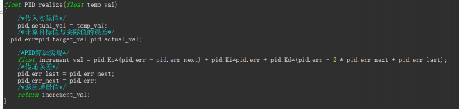
Stepper Motor Closed-Loop Control System
/** * @brief Stepper Motor Braking * @param None * @retval None */void Set_Stepper_Stop(void){ /* Disable comparison channel */ TIM_CCxChannelCmd(MOTOR_PUL_TIM,MOTOR_PUL_CHANNEL_x,TIM_CCx_DISABLE); sys_status.stepper_running = 0;}/* * @brief Start Stepper Motor * @param None * @retval None */void Set_Stepper_Start(void){ /* Enable driver */ MSD_ENA(0); /* Enable comparison channel output */ TIM_CCxChannelCmd(MOTOR_PUL_TIM,MOTOR_PUL_CHANNEL_x,TIM_CCx_ENABLE); sys_status.MSD_ENA = 1; sys_status.stepper_running = 1;}/* * @brief Stepper Motor Incremental PID Control * @retval None * @note Called in the basic timer interrupt */void Stepper_Speed_Ctrl(void){ /* Encoder related variables */ static __IO int32_t last_count = 0; __IO int32_t capture_count = 0; __IO int32_t capture_per_unit = 0; /* Expected value after pid calculation */ static __IO float cont_val = 0.0f; __IO float timer_delay = 0.0f; /* Start pid calculation only when the motor is moving */ if((sys_status.MSD_ENA == 1) && (sys_status.stepper_running == 1)) { /* Calculate the number of encoder pulses within a single sampling time */ capture_count =(int)__HAL_TIM_GET_COUNTER(&TIM_EncoderHandle) + (encoder_overflow_count * ENCODER_TIM_PERIOD); /* The number of encoder pulses per unit time is passed as the actual value to the pid controller */ cont_val += PID_realize((float)capture_count);// Perform PID calculation /* Determine speed direction */ cont_val > 0 ? (MOTOR_DIR(CW)) : (MOTOR_DIR(CCW)); /* Take the absolute value of the expected value calculated */ timer_delay = fabsf(cont_val); /* Limit maximum startup speed */ timer_delay >= SPEED_LIMIT ? (timer_delay = SPEED_LIMIT) : timer_delay; /* Calculate the value for the comparison counter */ OC_Pulse_num = ((uint16_t)(T1_FREQ / ((float)timer_delay * PULSE_RATIO))) >> 1; printf("Actual Value: %d, Target Value: %.0f\r\n", capture_per_unit, pid.target_val);// Print actual and target values } else { /* Clear all parameters in the stopped state */ last_count = 0; cont_val = 0; pid.actual_val = 0; pid.err = 0; pid.err_last = 0; pid.err_next = 0; }}Defines some intermediate variables used for encoder speed measurement and PID calculation.
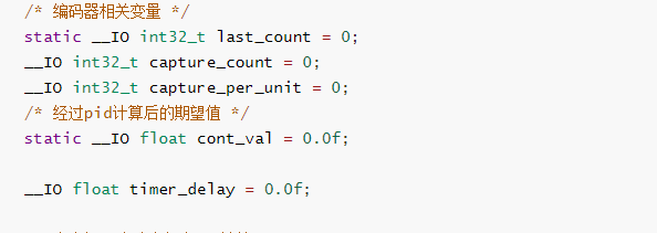
Judges the running status of the driver and motor; closed-loop control can only be executed when the driver is enabled and the motor is in motion.
if((sys_status.MSD_ENA == 1) && (sys_status.stepper_running == 1))Reads the encoder count value and calculates the count value within a single sampling period, capture_per_unit, in pulses per millisecond, which actually represents the frequency of the encoder pulses. For convenience in subsequent calculations, it is not written in terms of speed in revolutions per second;
capture_count =(int)__HAL_TIM_GET_COUNTER(&TIM_EncoderHandle) + (encoder_overflow_count * ENCODER_TIM_PERIOD);When the motor stops or changes from running to stopping, it is necessary to clear the intermediate values of the encoder readings and the accumulated data in the PID controller to avoid affecting the control effect when the motor starts again.
/* Clear all parameters in the stopped state */last_count = 0;cont_val = 0;pid.actual_val = 0;pid.err = 0;pid.err_last = 0;pid.err_next = 0;Execution Process
In the entire Stepper_Speed_Ctrl closed-loop control function, the parameters passed to PID and the output of PID are all based on the encoder’s data, which is the pulse frequency of the encoder. However, the actual controlled quantity is the speed of the stepper motor, which requires conversion.
The pulse frequency of the encoder, capture_per_unit, is multiplied by a coefficient PULSE_RATIO to obtain the required pulse frequency for the stepper motor. This coefficient is derived from the number of pulses required for the stepper motor to complete one revolution after subdivision, divided by the number of pulses emitted by the encoder in one revolution.
However, at this point, the frequency is still in milliseconds, and for convenience in subsequent calculations, it needs to be unified to seconds. Since the sampling period of this routine is 20ms, the unit conversion only requires multiplying by the number of samples in 1 second, which is 50.
After obtaining the required pulse frequency for the stepper motor, it is converted into a value that can be written into the capture compare register.
When the timer is configured in output compare mode, the pulse period of the stepper motor can be changed by modifying the value in the capture compare register, thereby changing the motor speed.
Timer Control
The basic timer TIM6 calls the closed-loop control program in a cyclic manner during its timing interrupt, with TIM6 configured to trigger an interrupt every 20ms, meaning that the sampling period for closed-loop control is 20ms.
void HAL_TIM_PeriodElapsedCallback(TIM_HandleTypeDef *htim){ /* Determine which timer triggered the interrupt */ if(htim->Instance == BASIC_TIM) { Stepper_Speed_Ctrl(); } else if(htim->Instance == ENCODER_TIM) { /* Determine the current counting direction */ if(__HAL_TIM_IS_TIM_COUNTING_DOWN(htim)) /* Down overflow */ encoder_overflow_count--; else /* Up overflow */ encoder_overflow_count++; }}Main Function
#include "main.h"#include <stdio.h>#include <stdlib.h>#include "usart.h"#include "stepper_init.h"#include "key.h"#include "led.h"#include "pid.h"#include "tim.h"#include "stepper_ctrl.h"#include "encoder.h"#include "protocol.h"extern _pid pid;extern int pid_status;/** * @brief Main function * @param None * @retval None */int main(void) { /* Initialize system clock to 72MHz */ SystemClock_Config(); /* Enable multiplex register clock */ __HAL_RCC_SYSCFG_CLK_ENABLE(); /* Set Interrupt Group Priority */ HAL_NVIC_SetPriorityGrouping(NVIC_PRIORITYGROUP_4); /* Initialize USART configuration mode to 115200 8-N-1, interrupt receive */ DEBUG_USART_Config(); protocol_init(); /* Initialize serial communication protocol */ HAL_InitTick(5); /* Key interrupt initialization */ Key_GPIO_Config(); /* LED initialization */ LED_GPIO_Config(); /* Initialize basic timer to generate an interrupt every 20ms */ TIMx_Configuration(); /* Encoder interface initialization */ Encoder_Init(); /* Stepper motor initialization */ stepper_Init(); /* Default stop the motor on power-up */ Set_Stepper_Stop(); /* PID algorithm parameter initialization */ PID_param_init(); /* Convert target speed to encoder pulse count as PID target value */ pid.target_val = TARGET_DISP * ENCODER_TOTAL_RESOLUTION; while(1) { /* Data reception processing */ receiving_process(); /* Scan KEY1 to start the motor */ if( Key_Scan(KEY1_GPIO_PORT,KEY1_PIN) == KEY_ON ) { Set_Stepper_Start(); } /* Scan KEY2 to stop the motor */ if( Key_Scan(KEY2_GPIO_PORT,KEY2_PIN) == KEY_ON ) { Set_Stepper_Stop(); } /* Scan KEY3 to increase target position */ if( Key_Scan(KEY3_GPIO_PORT,KEY3_PIN) == KEY_ON ) { /* Increase position by 2 revolutions */ pid.target_val += 8000; } /* Scan KEY4 to decrease target position */ if( Key_Scan(KEY4_GPIO_PORT,KEY4_PIN) == KEY_ON ) { /* Decrease position by 2 revolutions */ pid.target_val -= 8000; }} /** * @brief Timer update event callback function * @param None * @retval None */void HAL_TIM_PeriodElapsedCallback(TIM_HandleTypeDef *htim){ /* Determine which timer triggered the interrupt */ if(htim->Instance == BASIC_TIM) { Stepper_Speed_Ctrl(); } else if(htim->Instance == ENCODER_TIM) { /* Determine the current counting direction */ if(__HAL_TIM_IS_TIM_COUNTING_DOWN(htim)) /* Down overflow */ encoder_overflow_count--; else /* Up overflow */ encoder_overflow_count++; }} /** * @brief System Clock Configuration * The system Clock is configured as follow : * System Clock source = PLL (HSE) * SYSCLK(Hz) = 72000000 * HCLK(Hz) = 72000000 * AHB Prescaler = 1 * APB1 Prescaler = 2 * APB2 Prescaler = 1 * HSE Frequency(Hz) = 8000000 * HSE PREDIV1 = 2 * PLLMUL = 9 * Flash Latency(WS) = 0 * @param None * @retval None */void SystemClock_Config(void){ RCC_ClkInitTypeDef clkinitstruct = {0}; RCC_OscInitTypeDef oscinitstruct = {0}; /* Enable HSE Oscillator and activate PLL with HSE as source */ oscinitstruct.OscillatorType = RCC_OSCILLATORTYPE_HSE; oscinitstruct.HSEState = RCC_HSE_ON; oscinitstruct.HSEPredivValue = RCC_HSE_PREDIV_DIV1; oscinitstruct.PLL.PLLState = RCC_PLL_ON; oscinitstruct.PLL.PLLSource = RCC_PLLSOURCE_HSE; oscinitstruct.PLL.PLLMUL = RCC_PLL_MUL9; if (HAL_RCC_OscConfig(&oscinitstruct)!= HAL_OK) { /* Initialization Error */ while(1); } /* Select PLL as system clock source and configure the HCLK, PCLK1 and PCLK2 clocks dividers */ clkinitstruct.ClockType = (RCC_CLOCKTYPE_SYSCLK | RCC_CLOCKTYPE_HCLK | RCC_CLOCKTYPE_PCLK1 | RCC_CLOCKTYPE_PCLK2); clkinitstruct.SYSCLKSource = RCC_SYSCLKSOURCE_PLLCLK; clkinitstruct.AHBCLKDivider = RCC_SYSCLK_DIV1; clkinitstruct.APB2CLKDivider = RCC_HCLK_DIV1; clkinitstruct.APB1CLKDivider = RCC_HCLK_DIV2; if (HAL_RCC_ClockConfig(&clkinitstruct, FLASH_LATENCY_2)!= HAL_OK) { while(1); }}

↑ Hot Course, Limited Time Coupon! 🎉 Grab it Now ↑