15.2
Introduction to Interrupt Processes
When an interrupt occurs, it first passes through the IRQ register. When the IRQ register detects an interrupt, it sends an interrupt signal to the Nested Vectored Interrupt Controller (NVIC) of the central processor. When the NVIC detects the interrupt request, it suspends the corresponding interrupt service routine (ISR). After that, the eight registers that were running are pushed onto the stack, and once the stack operation is complete, the interrupt service program is activated. Finally, the previously pushed registers are popped from the stack, and the program that was running before the interrupt continues.
Process of Interrupt Preemption:
When an interrupt occurs, it first passes through the IRQ register. When the IRQ register detects an interrupt, it sends an interrupt signal to the Nested Vectored Interrupt Controller (NVIC) of the central processor. When the NVIC detects the interrupt request, it suspends the corresponding interrupt service routine (ISR). After that, the eight registers that were running are pushed onto the stack, and once the stack operation is complete, the interrupt service program is activated. At this point, if another interrupt source with a higher priority requests an interrupt, the corresponding interrupt service routine will be suspended. The currently running eight registers are then pushed onto the stack, and once the stack operation is complete, the interrupt service program is activated. After the interrupt service program finishes running, the previously pushed registers are popped from the stack, and the program that was servicing the previous interrupt continues. After the interrupt service program is completed, the previously pushed registers are popped from the stack, and the program that was running before continues.
15.3
Experiment: External Interrupt with Button
The importance of interrupts in embedded applications is undeniable; almost every controller has interrupt functionality. It is crucial for events to be handled in real-time. We designed a button to serve as a trigger source, allowing the controller to generate an interrupt and implement the task of controlling an LED in the interrupt service routine.
15.3.1
Hardware Design
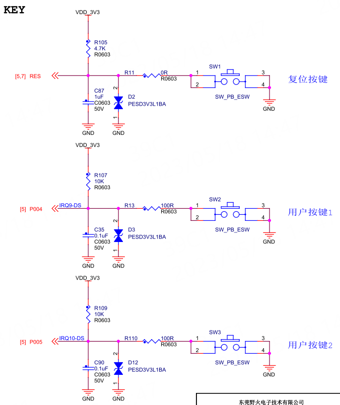
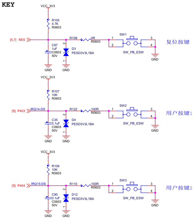
When the button is pressed, it connects the two pins of the button, and through circuit design, it can cause a level change on the pins when the button is pressed.
The button circuit design for the Wildfire Qiming 6M5 development board is as follows:
The button circuit design for the Wildfire Qiming 4M2 development board is as follows:
The button circuit design for the Wildfire Qiming 2L1 development board is as follows:
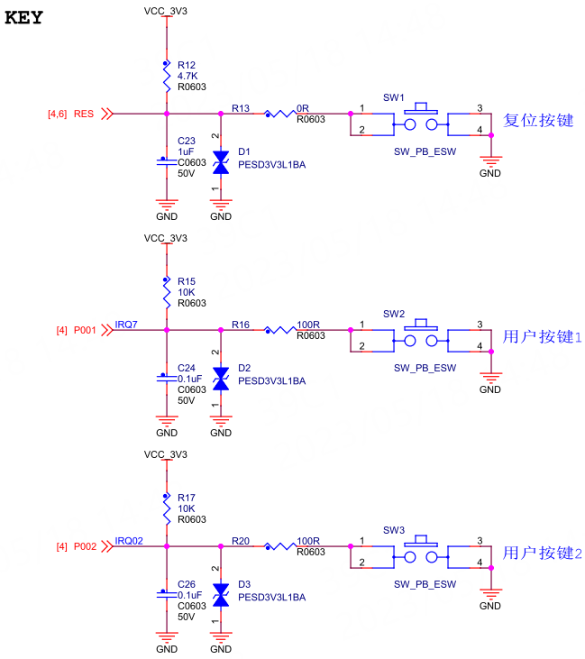
Among them, the RES button is the reset button for the development board’s chip, used to reset the MCU chip. The other two buttons are user-defined buttons that can be used to implement user-required functions.
In the button circuit design, the capacitor in parallel with the button serves as a hardware filter capacitor, which can help prevent false triggering caused by button bounce. In fact, users can also utilize the built-in digital filtering function of the IO pins of the Renesas RA MCU, allowing them to remove this capacitor and thus reduce the hardware cost of the circuit board.
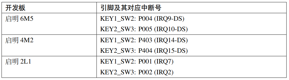
Table 3: Development Board Button Pin Allocation and Interrupt Numbers


Need Technical Support?
If you have any questions while using Renesas MCU/MPU products, you can scan the QR code below or copy the URL into your browser to access the Renesas Technical Forum for answers or online technical support.

https://community-ja.renesas.com/zh/forums-groups/mcu-mpu/
To be continued
Recommended Reading

Overview of Interrupt Applications in RA Series MCUs – Practical Guide to Developing with Renesas RA Series FSP Library (35)
NVIC Interrupt Configuration Firmware Library & RA6M5 – Practical Guide to Developing with Renesas RA Series FSP Library (36)
External Pin Interrupt – Practical Guide to Developing with Renesas RA Series FSP Library (37)