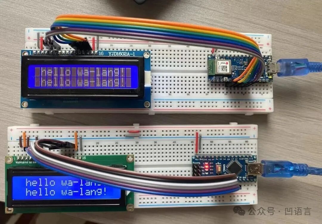
This is an example program for the LCD displayed at the 3rd Software Innovation Development Conference using Wa Language, as shown below:
1. LCD1602 Display
The LCD1602 (Liquid Crystal Display 1602) is a common character-type liquid crystal display module, where 1602 indicates that it can display 16 columns and 2 rows, totaling 32 characters. The LCD1602 has a built-in ASCII character set including letters, numbers, and common symbols. Similar displays include the LCD2004, which has 20 columns and 4 rows, and the LCD12864, which has 128 columns and 64 rows, but they all have 16 pins and similar control methods.
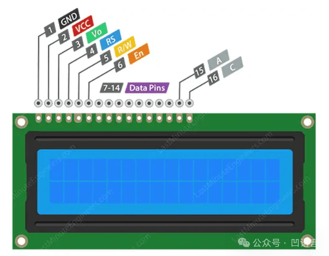
Below are the functions of each pin:
- VSS (Pin 1): This is the ground pin (0V).
- VDD (Pin 2): This is the power supply pin (available in 3V and 5V models).
- V0 (Pin 3): Contrast adjustment pin, connected to the middle pin of a potentiometer, with the other two terminals connected to VDD and GND, typically connected to a variable resistor to control voltage.
- RS (Register Select, Pin 4): Used to select the instruction register or data register. When this pin is low, it selects the instruction register for command mode. When this pin is high, it selects the data register for data mode.
- RW (Read/Write, Pin 5): Used to select read or write mode. When this pin is low, it activates write mode; when this pin is high, it activates read mode. It is generally set to write mode.
- E (Enable, Pin 6): Used to initiate data read/write operations by switching from high to low.
- D0 to D7 (Pins 7-14): These are data pins. D4-D7 are used for data transmission in both 4-bit and 8-bit modes. Typically, 4-bit mode is chosen to reduce the number of pins.
- A (Anode, Pin 15): Backlight LED positive. Generally needs to be connected to 5V through a resistor.
- K (Cathode, Pin 16): Backlight LED negative. Generally needs to be connected to GND.
The working principle of the LCD is to create images or text on the screen by precisely controlling light using liquid crystals. Each LCD has a backlight source that provides a stable light source. Special liquid crystals are sandwiched between two layers of polarizing glass.
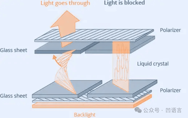
When current flows through these liquid crystals, their arrangement changes. This arrangement affects how light passes through the liquid crystals. Light first passes through the first layer of polarizing glass, then through the oriented liquid crystals, which twist the light to a specific angle. The second layer of polarizing glass allows or blocks the twisted light based on the twist angle. By precisely controlling the current flowing to different areas (or pixels) of the liquid crystals, the LCD can selectively allow or block light in specific areas. This allows images, numbers, or text to be displayed on the screen.
2. <span>arduino/lcd1602</span> Package
Based on the pin description documentation for the LCD1602, the following is organized:
// +---------------------------------------------------------------------+\n// | LCD1602 Module |\n// |-----+-----------------------+---------------------+-----------------+|\n// | Pin | Label | Connected To | Description | In Code |\n// |-----+-------+---------------+---------------------+-----------------+|\n// | 1 | GND | GND | Ground | - |\n// | 2 | VCC | 5V | Power Supply | - |\n// | 3 | VO | Potentiometer | Contrast Control | - |\n// | 4 | RS | D7 | Register Select | digitalWrite(RS)|\n// | 5 | RW | GND | Write Only (GND) | always LOW |\n// | 6 | E | D6 | Enable Signal | pulseEnable() |\n// | 11 | D4 | D5 | Data Bit 4 | write4bits() |\n// | 12 | D5 | D4 | Data Bit 5 | write4bits() |\n// | 13 | D6 | D3 | Data Bit 6 | write4bits() |\n// | 14 | D7 | D2 | Data Bit 7 | write4bits() |\n// +-----+-------+---------------+---------------------+-----------------+\nIn 4-bit write-only mode, the RW and D0-D3 pins are not needed, while GND/VCC/VO/RW/A/K have fixed wiring. Therefore, only 6 control pins need to be defined:
// LCD1602 Pin Definitions\nglobal (\n\tRS :i32 = 7\n\tE :i32 = 6\n\tD4 :i32 = 5\n\tD5 :i32 = 4\n\tD6 :i32 = 3\n\tD7 :i32 = 2\n)\nFirst, initialize the 6 pins to output mode (corresponding to LCD as input):
func LCDInit {\n\tarduino.PinMode(RS, arduino.OUTPUT)\n\tarduino.PinMode(E, arduino.OUTPUT)\n\tarduino.PinMode(D4, arduino.OUTPUT)\n\tarduino.PinMode(D5, arduino.OUTPUT)\n\tarduino.PinMode(D6, arduino.OUTPUT)\n\tarduino.PinMode(D7, arduino.OUTPUT)\n\tarduino.Delay(50) // Wait for LCD to start\n\t...\n}\nThen set it to 4-bit transmission mode:
func LCDInit {\n\t...\n\t// Initialize to 4-bit mode\n\twrite4bits(0x03)\n\tarduino.Delay(5)\n\twrite4bits(0x03)\n\tarduino.DelayMicroseconds(150)\n\twrite4bits(0x03)\n\twrite4bits(0x02) // Set 4-bit mode\n\t...\n}\nData or commands are sent through D4-D7 in 4-bit chunks, using the <span>write4bits</span> function:
func write4bits(value: byte) {\n\tarduino.DigitalWrite(D4, i32((value>>0)&0x01))\n\tarduino.DigitalWrite(D5, i32((value>>1)&0x01))\n\tarduino.DigitalWrite(D6, i32((value>>2)&0x01))\n\tarduino.DigitalWrite(D7, i32((value>>3)&0x01))\n\tpulseEnable()\n}\n<span>pulseEnable</span> function controls each 4-bit transmission by managing the state of the <span>E</span> pin:
func pulseEnable {\n\tarduino.DigitalWrite(E, arduino.LOW)\n\tarduino.DelayMicroseconds(1)\n\tarduino.DigitalWrite(E, arduino.HIGH)\n\tarduino.DelayMicroseconds(1)\n\tarduino.DigitalWrite(E, arduino.LOW)\n\tarduino.DelayMicroseconds(100) // Wait for command execution\n}\nFinally, complete the initialization tasks such as clearing the screen in the <span>LCDInit</span> function:
func LCDInit {\n\t...\n\t// Several basic settings\n\tcommand(0x28) // 4-bit, 2 lines, 5x8 dot matrix\n\tcommand(0x08) // Turn off display\n\tcommand(0x01) // Clear screen\n\tarduino.Delay(2)\n\tcommand(0x06) // Input mode: cursor moves right after write\n\tcommand(0x0C) // Display on, cursor off\n}\nAfter completing the LCD initialization with <span>LCDInit</span>, you can control the displayed content using commands and data. Below is the implementation of sending commands or data using <span>send</span>:
// Send a full byte in two 4-bit chunks (mode: 0 = command, 1 = data)\nfunc send(value, mode: byte) {\n\tarduino.DigitalWrite(i32(RS), i32(mode))\n\twrite4bits(value >> 4) // High four bits\n\twrite4bits(value & 0x0F) // Low four bits\n}\n<span>send</span> function sends data or commands to the LCD, where the <span>mode</span> parameter indicates whether it is a command or data, controlled internally by the <span>RS</span> pin. Based on the <span>send</span> function, you can encapsulate the <span>command</span> and <span>writeChar</span> functions for writing commands and data:
// Send instruction command to LCD (RS=0)\nfunc command(value: byte) {\n\tsend(value, byte(arduino.LOW))\n}\n\n// Write a character to current cursor position (RS=1)\nfunc writeChar(value: byte) {\n\tsend(value, byte(arduino.HIGH))\n}\nFor example, you can control the cursor position using commands. The cursor position for the first row is controlled by commands from 0x80 to 0x90, and for the second row from 0xC0 to 0xD0. The encapsulated <span>LCDSetCursor</span> function is as follows:
func LCDSetCursor(row, col: i32) {\n\tif row == 0 {\n\t\tcommand(byte(0x80 + col))\n\t} else {\n\t\tcommand(byte(0xC0 + col))\n\t}\n}\nThen display a character at the current row and column position:
func LCDWriteChar(ch: rune) {\n\twritelChar(byte(ch))\n}\nAlso, the command to clear the screen is 0x01:
func LCDClear {\n\tcommand(0x01)\n\tarduino.Delay(2)\n}\nAt this point, the encapsulation of the lcd1602 package is complete, and the external API specifications are as follows:
// LCD1602 Pin Definitions\nglobal (\n\tRS :i32 = 7\n\tE :i32 = 6\n\tD4 :i32 = 5\n\tD5 :i32 = 4\n\tD6 :i32 = 3\n\tD7 :i32 = 2\n)\n\n// Initialize the LCD screen\nfunc LCDInit()\n\n// Display a character at the current position\nfunc LCDWriteChar(ch: rune)\n\n// Clear the screen\nfunc LCDClear()\n3. Arduino Example Program
Refer to the <span>waroot/examples/arduino-lcd1602</span> directory in the main repository of Wa Language for a simplified version of the program as follows:
// Copyright @2025 arduino-lcd1602 Author. All rights reserved.\n\nimport (\n\t"arduino/lcd1602"\n\t"syscall/arduino"\n)\n\nfunc init {\n\t// Initialize the screen\n\tlcd1602.LCDInit()\n}\n\nfunc Loop {\n\tconst s = "hello wa-lang!"\n\n\t// Clear the screen, redraw the string\n\tlcd1602.LCDClear()\n\tSayHello(0, 1, s)\n\tSayHello(1, 0, s)\n\n\t// Sleep for 500 milliseconds\n\tarduino.Delay(500)\n}\n<span>SayHello</span> starts displaying a string at the specified row and column position:
func SayHello(row, col: i32, s: string) {\n\tlcd1602.LCDSetCursor(row, col)\n\n\tfor i := 0; i < len(s); i++ {\n\tlcd1602.LCDWriteChar(i32(s[i]))\n\t}\n}\nThe Loop function will be continuously called, so you can achieve animation by combining clearing the screen and delays. For the complete example, please refer to the provided sample code.
4. Additional Benefits
The working principle of the above code can be referenced in the generated C code. Users can modify the implementation of the simulated host import functions for finer customization. Essentially, a complete Arduino C language project is generated, so theoretically, Wa Language can be compiled into a local executable program using a C language compiler.
Below is the execution effect of the <span>waroot/examples/hello</span> example on Windows:

5. Conclusion
This example is not complex in itself, but the technological evolution behind it took nearly three years, from the initial Wasm3 virtual machine to the wat2c tool derived from rewriting the wat backend, to finally running the entire chain.
Wa Language has added and improved support for the Arduino platform at the end of 2022 and the end of 2024. The technical solution at that time was to execute the wasm programs output by Wa Language through the Wasm3 virtual machine. However, the minimum hardware dependency of Wasm3 is ~64Kb Flash, which is weak for small memory microcontrollers. The development team used wat2c technology to eliminate the performance loss of Wasm3, finally allowing programs to run on Arduino Nano development boards with only 2KB of memory.
From the first five-year plan of “usable” to the second five-year plan of “easy to use”, this example is a reflection of “easy to use”. We remain open to any form of discussion and collaboration, looking forward to pushing for a new round of evolution together!