System Overview
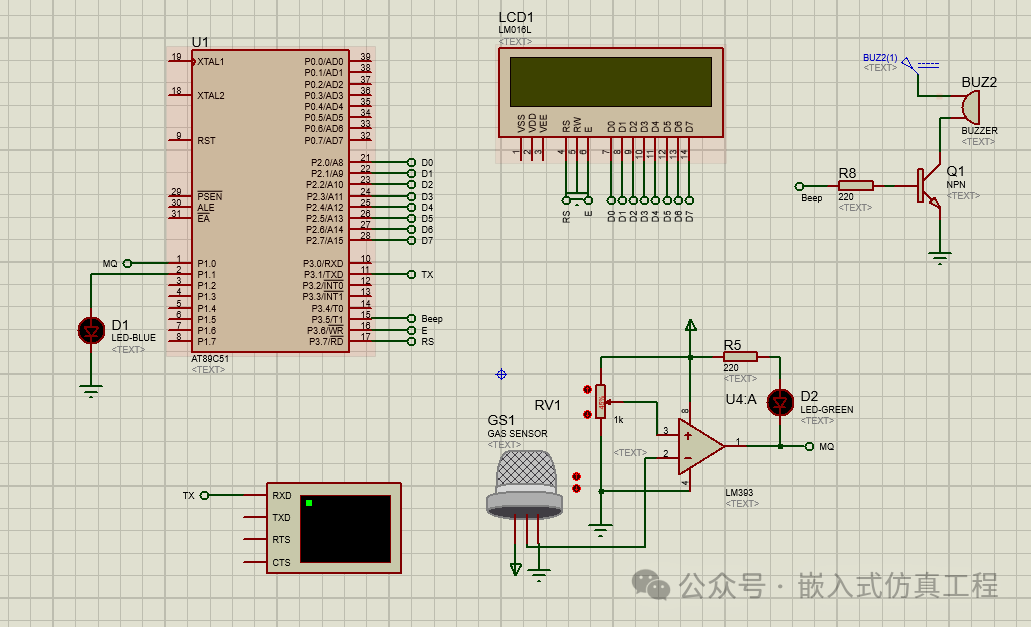
This gas leakage alarm system uses the AT89C51 microcontroller as the controller, the MQ-2 gas sensor as the detection element, and the LM016L LCD display as the output device, along with a buzzer and LED alarm light. When a gas leak is detected, the system displays a warning message on the LCD while triggering the buzzer and LED alarm.
Hardware Connections
-
LCD Connection:
-
P2.0-P2.7 connects to D0-D7 of LM016L
-
P3.6 connects to E (Enable) of LM016L
-
P3.7 connects to RS (Register Select) of LM016L
-
R/W of LM016L is grounded (write mode only)
-
Sensor and Alarm Devices:
-
P1.0 connects to MQ-2 gas sensor
-
P1.1 connects to alarm LED
-
P3.5 connects to buzzer
Source Code
Write application code and compile to generate HEX file
#include<reg51.h>
#define lcd P2
//functions’ declaration
void lcd_init();
void uc_init();
void character(unsigned char);
void cmd(unsigned char);
void string(unsigned char *);
void number(int);
void uart_init();
void gstring(unsigned char *p);
void Tx(unsigned char ch);
void bin_overflow_msg();
void delay(int);
void buzzer(unsigned char b);
sbit rs=P3^7;
sbit en=P3^6;
sbit buz=P3^5;
sbit bin=P1^0;
sbit alarm=P1^1;
unsigned char t=0;
void main()
{
uc_init();
lcd_init();
uart_init();
string(“Garbage Overflow”);
cmd(0xc0);
string(“Indicator.”);
delay(2000);
cmd(0x01);
cmd(0x80);
string(“System is Ready!”);
delay(1000);
cmd(0x01);
cmd(0x80);
for(;;)
{
while(bin==1)
{
cmd(0x80);
string(“No Overflow !”);
delay(2000);
}
if(bin==0)
{
delay(5000);
while(bin==0)
{
alarm=1;
cmd(0x01);
cmd(0x80);
string(“Gas leakage”);
cmd(0xc0);
string(“Detected !”);
delay(2000);
if(t==0)
bin_overflow_msg();
}
}
}
}
Proteus Simulation Instructions
-
Create a Proteus project and add the following components:
-
AT89C51 microcontroller
-
LM016L LCD display
-
MQ-2 gas sensor (can be simulated with a switch)
-
LED (alarm light)
-
Buzzer
Connect the components according to the above connection method
Load the HEX file generated from the above code into the AT89C51
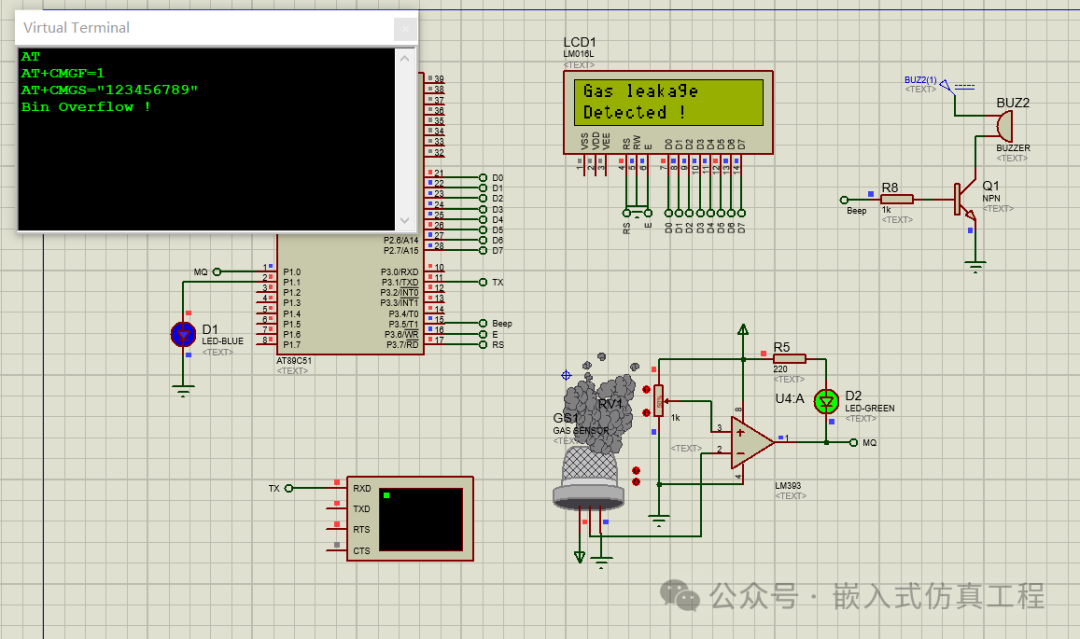
Run the simulation:
-
Under normal conditions, the LCD displays “Gas Detector” and “System Ready”
-
When simulating a gas leak (setting the MQ-2 sensor input low):
-
The alarm LED lights up
-
The buzzer sounds an alarm
-
The LCD displays “Gas leakage” and “Detected !”
-
The serial port sends a message, which can connect to a GMS module for remote alarm
Precautions
-
The MQ-2 sensor requires a warm-up time in practical applications; in simulation, its output can be simulated with a switch
-
The buzzer alarm sound can be adjusted by changing the delay time to alter the frequency
-
The information displayed on the LCD can be modified as needed
-
In practical applications, it may be necessary to add a gas concentration threshold adjustment feature
-
The precision of the delay function in the code is not high; in practical applications, consider using timer interrupts
Follow me (for operation reference, see the article: Send a message to the public account), click the blue text at the top “Embedded Simulation Project” or long press to recognize the QR code to follow
Reply in the public account
5114
After receiving, it will automatically send the link to this project in Keil, which has packaged the MQ-2 sensor library