
Knowledge Cool Pro 👆Learn about display industry knowledgeFind Xiao Ku! 2027th post
 In TFT-LCD display modules, we often encounter a situation where, “under the same image, especially a white image, when observing the same LCD display module from different angles, there are significant differences in the colors presented.” We usually refer to this phenomenon as:“Viewing-Angle Color Shift.”At this point, some readers may quickly recall similar issues they have encountered at work, feeling awkward about not knowing how to address them…Regarding the “Viewing-Angle Color Shift” issue, due to the differences in application fields and customer requirements for TFT-LCD display modules, some readers may have encountered it long ago; while others may not have encountered it until today.Of course, it is also possible that some have encountered it but have no impression of the “Viewing-Angle Color Shift” issue.So, in today’s article, we will discuss in detail. For those who have encountered it, consider this a refresher; for those who have not, I hope you read today’s article carefully so that when you encounter the same problem in the future, you will quickly know the solution.The article mainly revolves around the definition and phenomenon of Viewing-Angle Color Shift, the mechanism of its occurrence, and improvement strategies.01 Definition and Phenomenon of Viewing-Angle Color Shift① Definition of Viewing-Angle Color Shift:TFT-LCD Viewing-Angle Color Shift:It refers to the phenomenon where, after the observer deviates from the vertical direction of the LCD display module, the colors of the LCD display module deviate from the standard value from an objective perspective; and from a subjective perspective, there are significant visual differences in the colors of the LCD display module.In the industry, the color shift is usually quantified using the color coordinate deviation under the CIE1976 standard, denoted as Δu’v’. The calculation formula for the viewing-angle color shift is as follows:
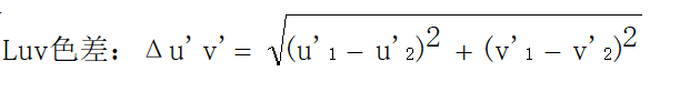 Where, u’1 represents the u’ value after the deviation angle,v’1 represents the v’ value after the deviation angle; u’2 represents the u’ value at the vertical angle,v’2 represents the v’ value at the vertical angle.Generally, when testing the viewing-angle color shift of TFT-LCD display modules, we divide it into four directions: up (U), down (D), left (L), and right (R), and three angles: 30°, 45°, and 60°.When the viewing-angle color shift test of the LCD display module is completed, a value will be obtained, such as Δu’v’ = 0.008. This result indicates that the viewing-angle color shift of the display module is relatively good, representing a JNCD value of 2.Quick Fact: 1 JNCD = 0.004JNCD (Just Noticeable Color Difference) is a unit commonly used to represent color deviation in display modules. The smaller the JNCD value,the smaller the color deviation of the display screen, and the better the image restoration effect.Of course, as the angle of deviation from the vertical view increases, the JNCD value will also increase, and the viewing-angle color shift will become more pronounced. This also indicates that many viewing-angle color shift issues are feedback based on large-angle testing and observation.② Phenomenon of Viewing-Angle Color Shift:For more professional readers, they can probably guess the phenomenon of viewing-angle color shift described in this article just by looking at the cover.If given a hint, such as: the viewing-angle color shift discussed in the article is related to the pixel structure of the TFT-LCD panel, it would be like a “pop quiz”…The phenomenon of viewing-angle color shift mentioned in this article is actually that when observing the LCD display module from a vertical angle, the colors appear normal; when observed from a certain angle, the colors of the image differ compared to the vertical view.To elaborate: when observing a white image on the LCD display module from a vertical angle, the colors appear normal; when observed from one side at a large angle, the image appears “blue”, and when observed from the other side at a large angle, the image appears “yellow”.
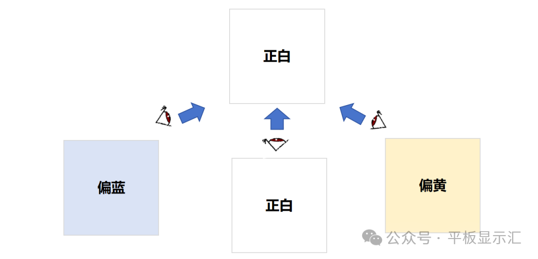 Illustration of Viewing-Angle Color Shift Phenomenon in LCD Display Modules02 Mechanism of Viewing-Angle Color ShiftNow that everyone should be clear about the definition and phenomenon of viewing-angle color shift, the specific mechanism of its occurrence has also been hinted at earlier, mainly related to the pixel structure and domain segmentation strategy of the LCD display panel.In the simplest pixel structure, each pixel typically has only one domain, which is commonly referred to as the “1P1D” structure, meaning “1 Pixel 1 Domain”, where all liquid crystal molecules within a single pixel have a single pre-tilt direction.The advantage of the “1P1D” pixel structure is that it has a high aperture ratio, a simple pixel structure and manufacturing process, and relatively low corresponding costs.However, its disadvantages are also very obvious: poor viewing angle performance, large viewing-angle color shift, and low contrast.Since liquid crystal molecules are optically anisotropic materials, before discussing the mechanism of viewing-angle color shift caused by the 1P1D pixel structure, it is necessary to understand two important concepts in TFT-LCD liquid crystal display panels:effective birefringence and optical path difference, phase retardation.① Effective Birefringence and Optical Path Difference:Due to the structure of liquid crystal molecules being “rod-like”, divided into “long axis” and “short axis”, they are optically anisotropic materials, which gives them birefringent properties.The refractive indices in the long axis and short axis directions of liquid crystal molecules are also different. Generally, the refractive index in the long axis direction is denoted as ne (e light), and the refractive index in the short axis direction is denoted as no (o light).The effective birefringence is generally represented as:Δneff; while the optical path difference OPD is represented as: OPD = Δneff*d, where d represents the thickness of the liquid crystal layer.
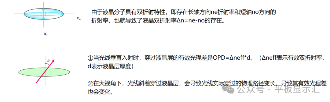 Illustration of Effective Birefringence and Optical Path Difference in Liquid Crystal Molecules② Phase Retardation:
When linearly polarized light passes through the liquid crystal layer, it can be decomposed into ordinary light (o light) and extraordinary light (e light). Due to the different propagation speeds of the two in the liquid crystal, a phase difference is generated upon exiting.
In TFT-LCD liquid crystal display panels,phase retardation is the core factor that causes color deviation in the image. Its calculation formula is as follows:
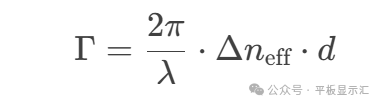
Where, λ represents the wavelength of light (nm), Δneff represents the liquid crystal birefringence, d represents the thickness of the liquid crystal layer,Δneff*d represents the optical path difference (nm), and the optical path difference directly determines the magnitude of the phase retardation.
After discussing effective birefringence and optical path difference, phase retardation, let’s formally discuss the mechanism of viewing-angle color shift caused by the 1P1D pixel structure:1) When the observation direction is perpendicular to the long axis of the liquid crystal molecules, the mechanism that leads to the “yellowing” of the image is as follows:a. The polarization direction is parallel to the long axis of the liquid crystal molecules, ne refractive index is high
b. The polarization direction is perpendicular to the short axis of the liquid crystal molecules, no refractive index is low
c. The effective refractive index Δneff = ne – no is at its maximum
d. The optical path difference OPD = Δneff*d increases, leading to a large phase retardation. At the same time, blue light has a shorter wavelength, and under the same optical path difference OPD, the phase retardation is larger, which means it is “dragged” further, leading to a sharp drop in blue light transmittance; red light has a longer wavelength and is “dragged” closer.
Due to the reduction of blue light, red and green light dominate, resulting in the image appearing yellow when observed from a large angle.
2) When the observation direction is parallel to the long axis of the liquid crystal molecules, the mechanism that leads to the “blueing” of the image is as follows:
a. The polarization direction is perpendicular to the long axis of the liquid crystal molecules, only exciting o light, the refractive index remains constant at no
b. The effective refractive index Δneff is close to 0
c. The optical path difference OPD = Δneff*d decreases, and the phase retardation significantly reduces; red light has a long wavelength, and the phase retardation is small, leading to a decrease in red light transmittance; while blue light has a short wavelength and still has a certain modulation capability, thus blue light transmittance is high, resulting in the image appearing blue when observed from a large angle.
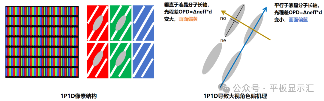 Illustration of Mechanism of Viewing-Angle Color Shift Caused by 1P1D Pixel Structure03 Improvement Strategies for Viewing-Angle Color ShiftAfter understanding the mechanism of viewing-angle color shift in LCD display panels with a 1P1D pixel structure, the corresponding improvement strategies are also relatively easy to understand. The improvement plan still starts from:the pixel structure and domain segmentation strategy of the LCD display panel.Common pixel structures and domain segmentation strategies for IPS mode LCD panels include three types: 1P1D, 1P2D, and 2P2D.These represent:1 pixel point with only 1 domain direction, 1 pixel point with 2 domain directions, and 2 pixel points with 2 domain directions.The 1P2D and 2P2D pixel structures significantly improve the large viewing-angle color shift of LCD display modules. The specific improvement mechanism is the same, and we will elaborate using the 1P2D pixel structure:1) When observing the LCD display panel from the left side at a large angle:
The optical path difference OPD = Δneff*d increases when parallel to the long axis of the liquid crystal molecules;
It decreases when perpendicular to the long axis of the liquid crystal molecules.
The arrangement of liquid crystals with two domain directions will cancel out the increase and decrease in optical path difference; thus, there is no color shift phenomenon when observing the image from the left side at a large angle.
2) When observing the LCD display panel from the right side at a large angle:
It decreases when perpendicular to the long axis of the liquid crystal molecules;
It increases when parallel to the long axis of the liquid crystal molecules..
The arrangement of liquid crystals with two domain directions will also cancel out the increase and decrease in optical path difference; thus, there is no color shift phenomenon when observing the image from the right side at a large angle.
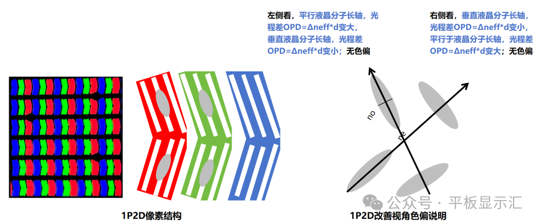 Illustration of 1P2D Pixel Structure and Mechanism for Improving Viewing-Angle Color ShiftOf course, with the continuous advancement of technology, various panel manufacturers have also introduced the 1P4D pixel structure, which can further optimize the display effect at large angles.
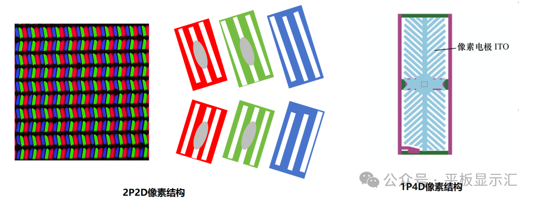 Illustration of 2P2D and 1P4D Pixel StructuresBy this point in the article, most readers should have a clear understanding of the common three pixel structures, the reasons affecting the large viewing-angle color shift of LCD display modules, and the improvement mechanisms.So, what specific advantages and disadvantages do these three pixel structures have? Due to the length of the article, I will summarize them as follows:
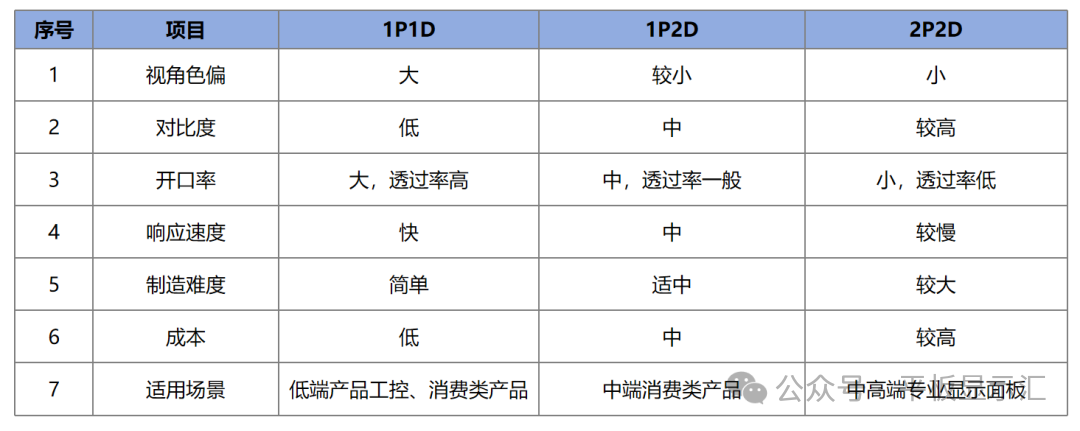 Comparison of Advantages and Disadvantages of Three Common Pixel StructuresSource: Flat Panel Display ExchangeEND