In industrial automation systems, sensors act as the “eyes” and “ears,” responsible for collecting key signals such as temperature, pressure, and position; while PLCs serve as the “brain,” receiving sensor signals and controlling actuator actions. The stability of their connection directly determines the reliability of the entire system. Today, we will provide a step-by-step guide on connecting PLCs with common types of sensors, covering everything from wiring to parameter settings, making it easy for beginners to get started.
1. Understanding Sensor Classification: Two Core Parameters to Know Before Connecting
Before wiring, it is essential to clarify the sensor’s “signal type” and “power supply method,” which are the basis for selecting the connection scheme:
- By signal type::
1) Digital sensors (only have two states: “on/off,” such as photoelectric switches and proximity switches);
2) Analog sensors (output continuously varying signals, such as temperature sensors and pressure sensors).
- By power supply method::
1) DC power supply (most common, such as DC 24V, compatible with most PLC input terminals);
2) AC power supply (such as AC 220V, need to check if the PLC input terminal supports it, usually requires an external relay for conversion).
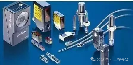
Diagram of Sensor Classification
2. Digital Sensor Connection Schemes (Most Common! Includes 3 Classic Cases)
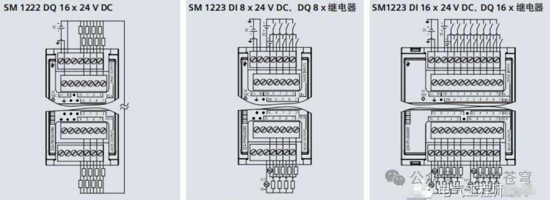
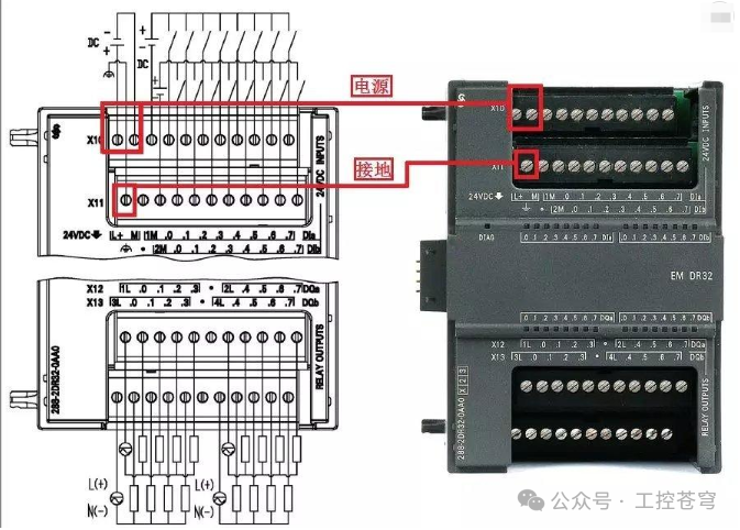
Digital sensors output “high/low” or “switch signals,” which can be directly connected to the PLC’s digital input terminals (I terminals) without the need for additional modules. Below are three of the most common connection scenarios:
Case 1: NPN Proximity Switch (DC 24V, Normally Closed)
NPN sensors are the “main force” in industrial sites, characterized by “outputting high level when no object is detected, and low level when an object is detected” (the normally closed type is the opposite).
Wiring Steps:
- Power Circuit: Connect the sensor “V+” to the positive terminal of DC 24V, and “V-” to the negative terminal of DC 24V;
- Signal Circuit: Connect the sensor “OUT” (output terminal) to the PLC digital input terminal (such as I0.0), and connect the PLC input terminal’s “common terminal (COM)” to the negative terminal of DC 24V.
(Insert NPN proximity switch wiring diagram here: use different colored wires to mark “power line (red: V+, black: V-)” “signal line (yellow: OUT→I0.0)” “common line (blue: PLC COM→24V-)”; highlight the “PLC input terminal area” in red, and label “NPN type: OUT→I terminal, COM→24V-“.)
Notes:
- If the sensor is a “normally open type,” then “OUT has no signal when no object is detected, and outputs low level when an object is detected.” The wiring method remains unchanged, but the logic in the PLC program needs to be adjusted;
- If the PLC input terminal is a “sourcing input” (such as Siemens S7-1200), the NPN sensor wiring is fully compatible; if it is a “sinking input,” the sensor “OUT” should be connected to the PLC COM terminal, and the PLC I terminal should be connected to 24V+, which essentially reverses the current flow direction, so be careful to distinguish.
Case 2: PNP Photoelectric Switch (DC 24V, Normally Open)
PNP sensors are the opposite of NPN sensors, characterized by “outputting high level (DC 24V) when an object is detected, and low level when no object is detected.”
Wiring Steps:
- Power Circuit: Connect the sensor “V+” to the positive terminal of DC 24V, and “V-” to the negative terminal of DC 24V;
- Signal Circuit: Connect the sensor “OUT” to the PLC digital input terminal (such as I0.1), and connect the PLC input terminal’s “common terminal (COM)” to the positive terminal of DC 24V.
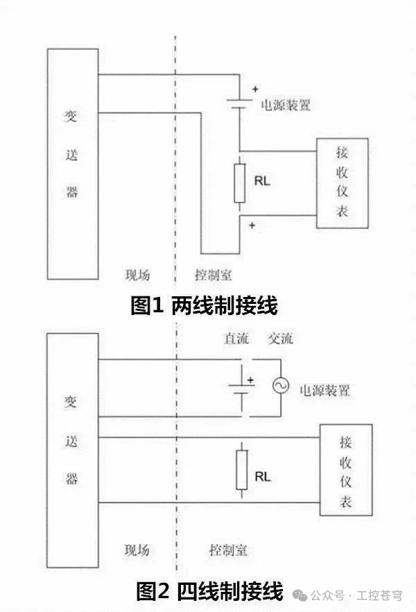
Key Differences:
- NPN sensors are “pull-down signals” (OUT connects to I terminal, COM connects to 24V-), while PNP sensors are “pull-up signals” (OUT connects to I terminal, COM connects to 24V+);
- If unsure of the sensor type, use a multimeter to measure the voltage between “OUT” and “V-“: when an object is detected, the NPN type voltage approaches 0V, while the PNP type voltage approaches 24V.
Case 3: AC 220V Limit Switch (Normally Closed)
Some older equipment uses AC 220V limit switches, while PLC input terminals usually only support DC 24V, requiring the use ofintermediate relays to convert the signal.
Wiring Steps:
- Relay Power Supply: AC 220V live wire → limit switch → intermediate relay coil → AC 220V neutral wire;
- PLC Signal Circuit: DC 24V positive → intermediate relay normally open contact → PLC input terminal (such as I0.2) → PLC COM terminal → DC 24V negative.
(Insert wiring diagram with relay here: label the left side “AC 220V circuit (limit switch + relay coil)” and the right side “DC 24V PLC circuit (relay contact + I0.2)”; highlight the “intermediate relay: achieving AC/DC signal conversion” in red.)
Core Function:
- The intermediate relay acts as a “signal converter,” preventing high voltage AC 220V from directly entering the PLC, thus protecting the PLC input terminals;
- If the limit switch is a “normally open type,” then “when triggered, the relay coil is energized, the contact closes, and PLC I0.2 receives power.”
3. Analog Sensor Connection Schemes (Require Analog Modules, Includes 2 Typical Scenarios)
Analog sensors output “4-20mA current” or “0-10V voltage” signals, which need to be connected to the PLC’sanalog input module (AI module), and then converted to actual physical quantities (such as temperature, pressure) through the PLC program.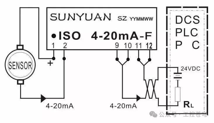
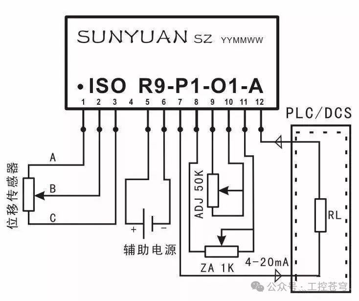
Case 1: 4-20mA Pressure Sensor (Two-Wire)
Two-wire sensors are the mainstream in industry, characterized by “power and signal sharing two wires,” making wiring simple and resistant to interference.
Wiring Steps:
- Module Power Supply: Ensure the PLC analog module is properly connected to a DC 24V power supply (usually shared with the PLC host);
- Sensor Wiring: Connect the sensor “+” terminal to the analog module AI channel (such as AI0) ” +” terminal, and the sensor “-” terminal to the analog module AI channel “-” terminal;
- Note: Two-wire sensors do not require additional power supply, as the power is provided by the analog module (the module has a 24V power supply circuit inside).
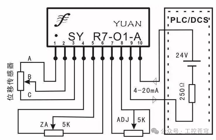
PLC Parameter Settings (Taking Siemens S7-1200 as an Example):
- Open the TIA Portal software, go to “Device Configuration” → “Analog Module” → “Properties”;
- In the “Input” tab, select “Signal Type” as “Current” and “Range” as “4-20mA”;
- In the program, use the “NORM_X” instruction to convert 4-20mA to a normalized value of 0-1.0, and then use the “SCALE_X” instruction to convert it to the actual pressure value (e.g., 0-10MPa).
Case 2: 0-10V Temperature Sensor (Three-Wire)
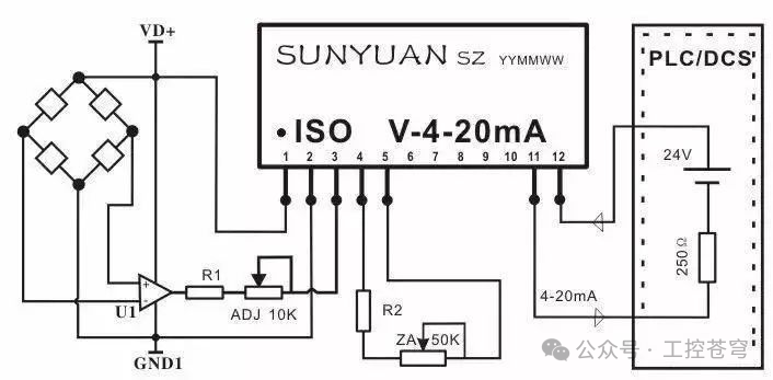
Three-wire sensors require “separate power supply,” with the signal outputting 0-10V voltage, suitable for short-distance transmission (voltage signals are less resistant to interference than current signals).
Wiring Steps:
- Sensor Power Supply: Connect DC 24V positive to the sensor “V+” and DC 24V negative to the sensor “V-“;
- Signal Circuit: Connect the sensor “OUT” (signal terminal) to the analog module AI channel (such as AI1) ” +” terminal, and connect the sensor “V-” to the analog module AI channel “-” terminal (common ground to reduce interference).
Interference Prevention Tips:
- It is recommended that the transmission distance of voltage signals does not exceed 10 meters; if it exceeds, switch to 4-20mA current signals;
- Use “shielded twisted pair” for signal lines, with one end of the shield grounded (grounded on the PLC side) and the other end left floating to reduce electromagnetic interference.
4. Special Sensor Connection Schemes (Require Additional Configuration, Includes 2 Practical Scenarios)
Case 1: RS485 Communication Temperature and Humidity Sensor (Modbus Protocol)
Communication sensors communicate with PLCs via the “RS485 bus,” allowing multiple parameters (such as temperature and humidity) to be transmitted simultaneously without occupying multiple AI channels, suitable for centralized monitoring of multiple sensors.
Wiring Steps:
- Hardware Connection: Connect the sensor “A” terminal to the “A” terminal of the PLC RS485 module, and connect the sensor “B” terminal to the “B” terminal of the PLC RS485 module (ensure A connects to A and B connects to B; reverse connections will result in communication failure);
- Power Supply: The sensor should be connected to a separate DC 24V power supply (V + connects to 24V+, V – connects to 24V-).
RS485 Communication Wiring Diagram: Label “RS485 Module (A/B Terminals)” and “Sensor (A/B Terminals)”; use dashed lines to indicate “Bus-type connection: multiple sensors can be connected in series, A/B terminals connected in sequence”; highlight “Termination Resistor: connect 120Ω termination resistors at both ends of the bus if the distance exceeds 100 meters” in red.)
PLC Communication Configuration (Taking Mitsubishi FX5U as an Example):
- Open the GX Works3 software, go to “Parameters” → “Communication Settings,” select the “Modbus RTU” protocol, set the “Baud Rate” (e.g., 9600bps), “Data Bits” (8 bits), “Stop Bits” (1 bit), and “Parity Bit” (none), ensuring they match the sensor parameters;
- In the program, use the “MODBUS_RTU_MASTER” instruction to set the sensor slave address (e.g., address 1), register address (e.g., temperature stored at 40001, humidity stored at 40002), and convert the read data to actual values.
Case 2: Encoder (Incremental, AB Phase)
Encoders are used to detect motor speed and equipment position, outputting AB phase pulse signals, which need to be connected to the PLC’shigh-speed counting module or the PLC’s built-in high-speed counter terminals.
Wiring Steps (Taking Siemens S7-200 SMART as an Example):
- Connect the encoder “V+” to the positive terminal of DC 24V, and “GND” to the negative terminal of DC 24V;
- Connect the encoder “A phase” to the PLC high-speed counter terminal (such as I0.0), and “B phase” to the PLC high-speed counter terminal (such as I0.1);
- If a reset signal is needed, connect the encoder “Z phase” to the PLC terminal (such as I0.2).
PLC Program Key Points:
- Enable the high-speed counter in the PLC (such as HC0), and select the “AB phase quadrature counting” mode to simultaneously detect speed and direction;
- In the program, calculate the equipment position using the “HC0 current value” (for example, if the encoder resolution is 1000 pulses/revolution and the current value is 5000, then the equipment has turned 5 revolutions).
5. Connection Pitfalls: 5 Essential Tips for Beginners
- Power Supply Matching:The sensor power supply voltage must match the specifications (e.g., connecting a DC 24V sensor to AC 220V will burn it out), and the PLC input terminal voltage must match the sensor signal voltage;
- Polarity Must Not Be Reversed:The polarity of the NPN/PNP sensor’s “OUT” and the PLC I terminal and COM terminal must not be reversed; otherwise, the PLC will not detect the signal;
- Common Ground is Key:Analog sensors and communication sensors must be “common grounded” with the PLC (sensor V – connected to PLC COM terminal); otherwise, signal drift will lead to inaccurate data;
- Interference Prevention Measures:Power lines and signal lines should be routed separately (avoid parallel wiring), and use shielded twisted pairs for analog and communication lines, with the shield grounded at one end;
- Test Before Connecting:Before wiring, use a multimeter to measure the sensor output signal (e.g., the voltage between OUT and V – when the NPN sensor is triggered) to confirm the sensor is functioning properly before connecting it to the PLC.
Summary: The “Three-Step Method” for Sensor Connections
Regardless of the type of sensor, the connection can be performed using the “three-step method”:
1) Check the specifications: Confirm the sensor’s “signal type (digital/analog)” “power supply voltage” “output method (NPN/PNP/4-20mA)”;
2) Select the wiring scheme: Digital signals connect directly to I terminals, analog signals connect to AI modules, and high voltage/communication types require relays/communication modules;
3) Test the signal: After wiring, power on and test, using the PLC’s online monitoring function to check if the input signal is normal (whether the digital I terminal is 1, and whether the analog AI value is within a reasonable range).
If you found this helpful, please give a thumbs up and follow us! ^_^