1. Example Description
1. Physical Case Description
Currently, there is a Wecon touch screen connected to a FX3U PLC, which is connected to a stepper motor. We need to write a control program to manage the stepper motor. (The stepper motor has a step angle of 1.8 degrees, a pitch of 2mm, and a subdivision setting of 4; the PLC I/O port definitions are: X5 is the negative limit, X4 is the origin, and X3 is the positive limit).
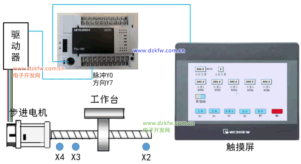 2. Control Requirements:
1) In manual mode, achieve automatic forward and reverse rotation.
2) Pressing the return to origin button should automatically return to the origin, and only after returning to the origin can automatic mode be activated.
3) In automatic mode, after returning to the origin, pressing the start button will cause the motor to move to the set positions (Position 1 -> Position 2 -> Position 3 -> Position 4 -> Position 5 -> Position 1) in a continuous loop.
4) Pressing the emergency stop button will immediately stop the stepper motor. The origin return command must be executed again.
5) When the pause button is pressed, the device stops, and pressing the start button again will resume operation.
2. Equipment Component Selection and I/O Layout
1. Electrical Component Selection List: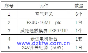 2. PLC I/O Allocation: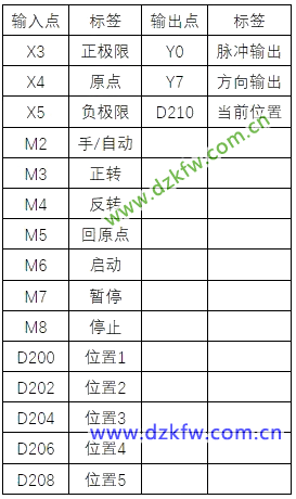
3. Wiring of PLC and Stepper Motor Driver
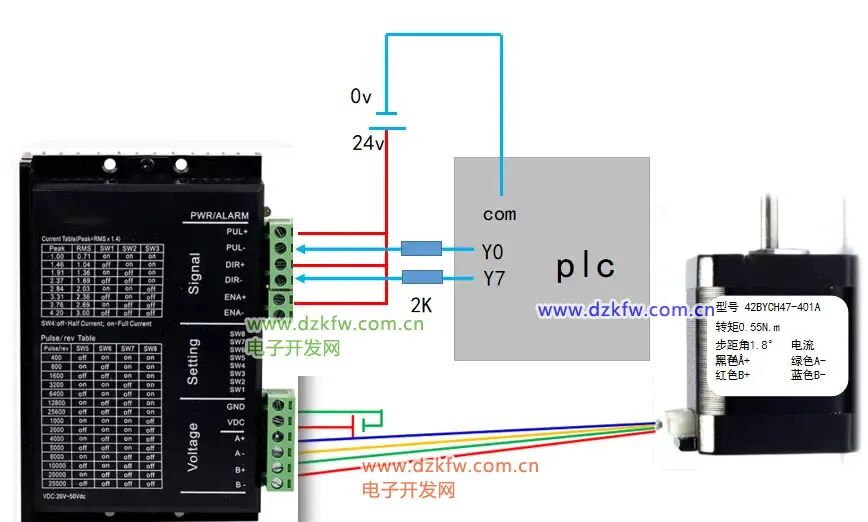
4. Ladder Diagram Program Development
1. Manual Control Program Description: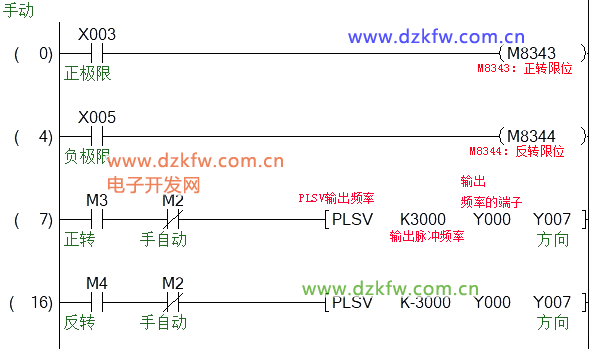 2. Origin Return Program Description:
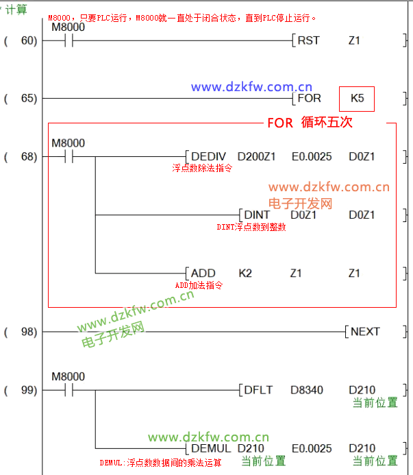
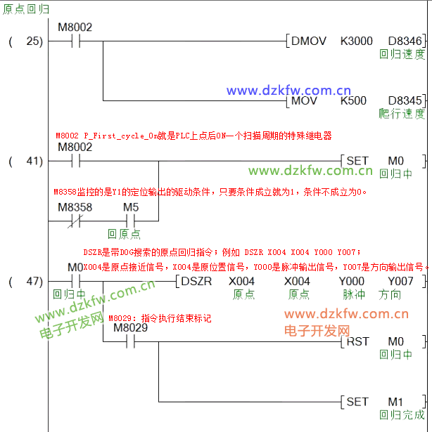 3. Data Calculation Program Description:
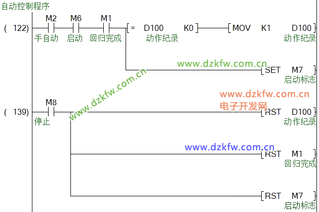
 4. Automatic Control Start/Stop Program:
 5. Sequential Control: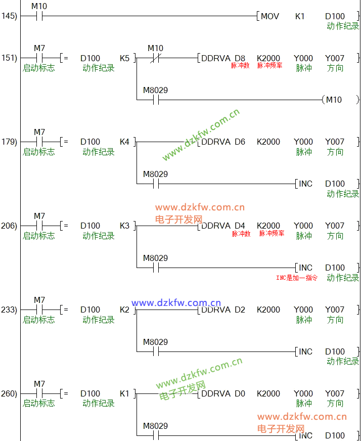
The actions need to be written in reverse order, with the first step written last. When the action is completed, M8029 will be activated, using INC to increment D100 by 1, and the same applies to each subsequent step; when reaching the fifth step, M8029 activates the M10 coil, and the normally open contact of M10 is written above this line of code, using the MOV instruction to reset D100 back to the first step. This is done to separate the actions into different scan cycles, ensuring that the fifth step’s action and the first step’s positioning command do not run in the same scan cycle.
When creating the button for M7 on the touch screen, select the reset button. When the stop button is pressed, M7 will be disconnected, and the next time the start button is pressed, M7 will be reactivated, and the operation will resume.
This concludes our case study. Here is a thought-provoking question for everyone: If you need to set up a speed input box on the touch screen, with the unit in mm/s, to adjust the speed, how would you write the program?
Source: Electronic Development Network.
Previous Recommendations
In a harsh world, private work~ After fixing the machine, the boss doesn’t want to pay…
Selecting the corresponding inverter power directly based on motor power (kW) may lead to issues.
FANUC Robot—Method for Zero Point Calibration
Standardization of Modbus RTU Master Communication in Mainstream PLCs
Wiring was done, but it burned out after 5 minutes of power on, fined 1000!

Share, view, and like; at least I want to have one!