Three Common Pain Points on Site
During equipment debugging on site, one often encounters scenarios where the cylinder numbers marked on the drawings do not match the output points in the program. After a long search, it is discovered that the IO table has already been modified; the program has thousands of lines, and adding a new function later makes one hesitant to make changes for fear of affecting the entire system; when equipment malfunctions, clients urge for quick fixes, yet one has to comb through the entire program to find the fault point.
The root of these problems often lies in the lack of a systematic workflow established during the initial design phase. Random IO allocation, chaotic program architecture, and rough debugging methods may seem to save time, but they actually lay a big pit for future maintenance. A standardized control system design process is not just for aesthetics; it is a solid effort that can genuinely improve project efficiency and reduce rework rates.
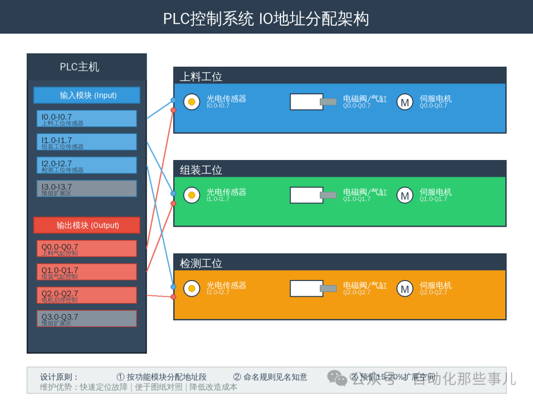
IO Allocation: Address Planning Determines Future Maintenance Costs
Partitioning is the Basic Principle
IO addresses should not be written arbitrarily. It is recommended to allocate address segments according to functional modules: input signals should be categorized by detection type (photoelectric sensors, limit switches, pressure switches, etc.), and output signals should be categorized by actuators (cylinders, motors, indicator lights, etc.). For example, I0.0-I0.7 can be allocated to the sensors at the loading station, while I1.0-I1.7 can be allocated to the assembly station, and outputs Q0.0-Q0.7 correspond to the cylinders at the loading station. The benefit of this approach is that if a problem occurs at a certain station, the corresponding address segment can be quickly located.
Naming Rules Should Be Intuitive
Address symbols should not use simple identifiers like Input1, Output2. It is recommended to use a “location + function + number” format, such as “UpStation_PhotoSensor_01” (photoelectric sensor 1 at the loading station) or “Asm_Cylinder_Clamp” (clamping cylinder at the assembly station). Although this requires typing a few more letters initially, three months later, when reviewing the program or handing it over to other engineers, it will be immediately understandable without repeatedly checking the IO table.
Reserving IO is Not Wasteful but Visionary
At least 20% of IO points should be reserved for each functional area. Non-standard equipment often requires changes in requirements; if a client suddenly needs to add a sensor or install an additional cylinder, it can be troublesome if the IO is already fully allocated. By reserving in advance, modifications can be made by simply adding a few lines of code in the program, and the wiring on site can be easily handled.
Program Architecture: Modularity to Adapt to Changing Requirements
Main Program Only for Scheduling, Functions in Subprograms
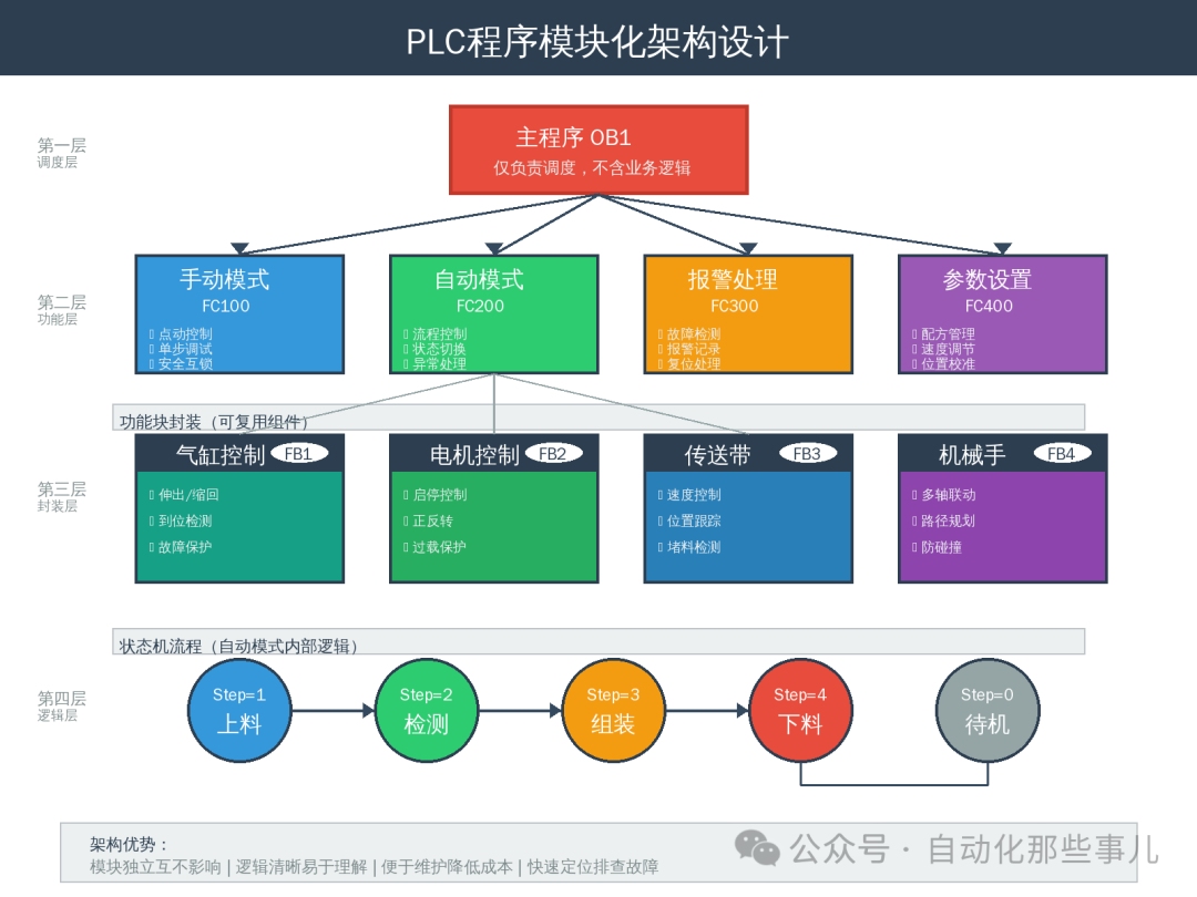
The main program (OB1) should not be cluttered with specific logic; it should only be responsible for calling various function blocks. For example, the manual mode calls FC100, the automatic mode calls FC200, and alarm handling calls FC300. Each subprogram corresponds to an independent function with clear internal logic. The advantage of this approach is that modifying a certain function will not affect other parts, and during debugging, a specific subprogram can be tested independently.
Utilize Function Blocks to Encapsulate Repetitive Logic
If there are multiple cylinders or motors in the project, do not write the control logic for each one separately. Encapsulate the extending, retracting, and position detection of the cylinders into an FB block, and encapsulate the start, stop, and fault protection of the motors into another FB block. When calling, simply pass different IO addresses and parameters. This not only reduces the amount of code but also standardizes the control logic; once one cylinder is adjusted correctly, others are unlikely to have issues.
State Machine Architecture is Suitable for Complex Processes
For multi-step automation processes, it is recommended to use state machine programming. Define a step variable (Step), with each step corresponding to a state value: Step=1 for loading, Step=2 for detection, Step=3 for assembly, etc. Clearly outline what needs to be done in each state, the completion conditions, and where to jump next. The advantage of this architecture is that the process is clear at a glance, and during debugging, one can force a jump to a specific step, making it easy to determine where the problem lies.
Debugging Methods: Systematic Approaches for Quick Fault Diagnosis
Segment Testing is Better than Full System Testing
Do not wait until all programs are written before powering on for debugging. It is recommended to first test single-point IO (force input/output to verify wiring and address correctness), then test individual actions (cylinder extension/retraction, motor forward/reverse), followed by single-step processes, and finally run the entire automated program. This way, if a problem arises, it can be immediately identified as a hardware or program issue, a logical error, or a timing problem. Jumping straight into automation can lead to a wide range of troubleshooting, which is highly inefficient.
Make Full Use of Monitoring and Forcing Tables
During debugging, establish a dedicated monitoring table that includes key signals (sensor status, cylinder position, step variables, current timer values). When issues arise, one can see the changes in various signals in real-time without having to check each variable individually. The forcing table is used to simulate signals; for example, if a sensor is faulty, it can be forced to input ON, allowing other parts to be debugged first. However, remember that forcing functions should only be used for debugging, and all forces must be cleared before delivery to avoid potential hazards.
Establish a Habit of Recording Faults and Comments
Each time a problem occurs, record the fault phenomenon, troubleshooting process, final cause, and solution. This way, similar situations can be resolved quickly in the future. Key logic in the program should be commented, especially for special handling (why the delay is 2 seconds, why interlocks are added here). Comments are not just for the current self but for the self who may forget details in six months and for colleagues who may take over the project.
System Design Determines the Quality Ceiling of the Project
From IO allocation to program architecture and debugging methods, each link has its own rules. Spending a little more time on standardized design in the early stages can save multiple times the time in debugging and maintenance later. Whether the equipment can run stably, respond quickly to changes in requirements, and recover swiftly from faults largely depends on the robustness of the control system design.
For frontline engineers, these methods are not theoretical but practical experiences validated through countless on-site debugging sessions. Mastering a systematic design process allows one to progress from a level of “it just needs to run” to a professional level of “easy maintenance, easy expansion, and minimal rework.” This process has no shortcuts; it requires conscious training and accumulation in each project to ultimately form one’s own work standards.