Chapter 6 GICv3 Architecture and Interrupt Handling Practice
Section 4 Complete Configuration Practice of Domestic Chip GICv3
6.4.1 In-depth Analysis of the Complete Interrupt Handling Process
In the Cortex-R52+ AArch32 architecture, the interrupt handling process involves a close collaboration between the GICv3 architecture and the processor’s exception model.
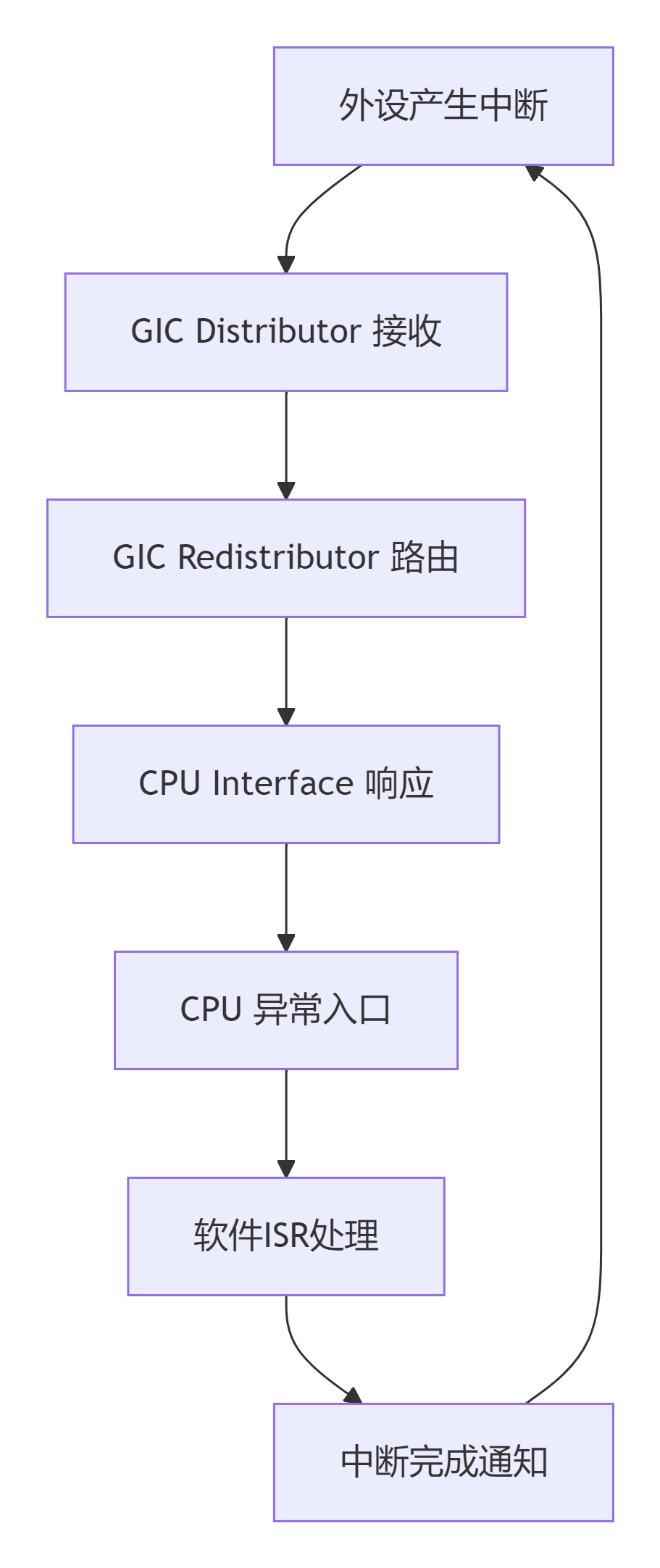
Stage 1: Interrupt Triggering and Dispatching
When a peripheral generates an interrupt, the GICv3 distributor first processes:
// GICv3 hardware automatic handling sequence: 1. Peripheral sets interrupt status → 2. GIC identifies interrupt ID and type → 3. Enable and priority checkStage 2: Cortex-R52+ Exception Entry
When the interrupt reaches the CPU interface, the processor hardware automatically executes the exception entry sequence:

6.4.2 Cortex-R52+ AArch32 Exception Handling Mechanism
Register Groups and Exception Modes
The Cortex-R52+ uses the following register organization in AArch32 mode:
// General-purpose registers R0-R12: General-purpose registers R13 (SP): Stack pointer (each mode has an independent SP) R14 (LR): Link register (stores return address) R15 (PC): Program counter // Program status register CPSR: Current program status register SPSR_: Saved program status register (specific to exception modes) // Exception mode Banked registers SP_irq, LR_irq, SPSR_irq // IRQ mode SP_fiq, LR_fiq, SPSR_fiq // FIQ mode SP_svc, LR_svc, SPSR_svc // SVC mode SP_abt, LR_abt, SPSR_abt // Abort mode SP_und, LR_und, SPSR_und // Undefined modeAutomatic Hardware Operations on Exception Entry
When an IRQ exception occurs, the hardware automatically executes:
; Hardware automatic sequence: SPSR_irq = CPSR ; Save current state LR_irq = PC + 4 ; Save return address CPSR[4:0] = 0b10010 ; Switch to IRQ mode CPSR[7] = 1 ; Disable IRQ CPSR[6] = 1 ; Disable FIQ (if configured) PC = VBAR + 0x18 ; Jump to IRQ vector address6.4.3 Practical Configuration of Domestic Chip GICv3
Taking the domestic “THA6” R52+ chip as an example, this section demonstrates the complete GICv3 configuration process.
6.4.3.1 Basic Initialization of GICv3
// gicv3_core.c - AArch32 version #include "chip_gicv3.h" // GICv3 register base address definition #define GICD_BASE 0x30000000 #define GICR_BASE 0x30040000 #define GICR_STRIDE 0x20000 // Complete GICv3 initialization process void gicv3_init(void){ // Step 1: Configure the distributor gicd_init(); // Step 2: Configure all redistributors gicr_init_all(); // Step 3: Configure CPU interface gicc_init(); // Step 4: Global enable gicv3_enable();}6.4.3.2 Detailed Configuration of the Distributor
// Distributor initialization static void gicd_init(void){ volatile uint32_t *gicd = (volatile uint32_t *)GICD_BASE; uint32_t i; // 1. Globally disable the distributor gicd[GICD_CTLR / 4] = 0x0; __dsb(0xF); // Data Synchronization Barrier // 2. Set default target CPU for all SPI interrupts for (i = 32; i < 1020; i += 4) { gicd[GICD_IROUTERn(i) / 4] = 0x00000001; // Route to CPU0 } // 3. Set all interrupt priorities (medium priority 0x80) for (i = 0; i < 1020; i += 4) { gicd[GICD_IPRIORITYRn(i) / 4] = 0x80808080; } // 4. Configure all interrupts as Level-sensitive for (i = 0; i < 1020; i += 16) { gicd[GICD_ICFGRn(i) / 4] &= ~(0x3 << ((i % 16) * 2)); // Level-sensitive } __dsb(0xF); // Ensure configuration is complete}6.4.3.3 Redistributor Configuration
// Redistributor initialization static void gicr_init_all(void){ uint32_t cpu; // Iterate through all CPU core redistributors for (cpu = 0; cpu < MAX_CPUS; cpu++) { volatile uint32_t *gicr = (volatile uint32_t *)(GICR_BASE + cpu * GICR_STRIDE); // 1. Wait for the redistributor to be ready while ((gicr[GICR_WAKER / 4] & 0x4) != 0) { // Wait for ChildrenAsleep bit to be 0 } // 2. Configure SGI and PPI priorities gicr[GICR_IPRIORITYRn(0) / 4] = 0x80808080; // 3. Enable CPU interface gicr[GICR_WAKER / 4] &= ~0x2; // Clear ProcessorSleep // 4. Wait for enable to complete while ((gicr[GICR_WAKER / 4] & 0x4) != 0) { // Wait for ChildrenAsleep to clear } }}6.4.3.4 CPU Interface Configuration
// CPU interface initialization - using coprocessor instructions static void gicc_init(void){ uint32_t reg_val; // 1. Set priority mask (allow all priority interrupts) reg_val = 0xFF; __asm volatile("MCR p15, 6, %0, c12, c12, 0" : : "r" (reg_val)); // ICC_PMR_EL1 // 2. Configure binary point (BPR) reg_val = 0x0; // Lowest binary point __asm volatile("MCR p15, 6, %0, c12, c12, 3" : : "r" (reg_val)); // ICC_BPR1_EL1 // 3. Configure CTLR - separate acknowledge and end mode __asm volatile("MRC p15, 6, %0, c12, c12, 4" : "=r" (reg_val)); // ICC_CTLR_EL1 reg_val |= (1 << 1); // EOImode = 1 __asm volatile("MCR p15, 6, %0, c12, c12, 4" : : "r" (reg_val)); __dsb(0xF); __isb(0xF);}6.4.4 Specific Peripheral Interrupt Configuration Example
Taking the UART interrupt of the domestic chip as an example:
// uart_interrupt.c - AArch32 version #include "chip_uart.h" #include "gicv3_driver.h" #define UART_IRQ_ID 48 // Domestic chip UART interrupt ID // UART interrupt service function void __attribute__((interrupt("IRQ"))) uart_isr(void){ uint32_t irq_id; // Read interrupt ID (also acknowledge interrupt) __asm volatile("MRC p15, 6, %0, c12, c12, 0" : "=r" (irq_id)); // ICC_IAR1_EL1 // Handle UART interrupt if (uart_get_status() & UART_STATUS_RX_READY) { uint8_t data = uart_read_data(); uart_process_rx_data(data); } // Interrupt handling complete __asm volatile("MCR p15, 6, %0, c12, c12, 1" : : "r" (irq_id)); // ICC_EOIR1_EL1} // UART interrupt configuration void uart_interrupt_init(void){ // 1. Configure UART interrupt in GICv3 gic_set_interrupt_config(UART_IRQ_ID, GIC_INT_PRIORITY_MID, GIC_TARGET_CPU0, GIC_CONFIG_LEVEL); // 2. Enable UART interrupt in GIC gic_enable_interrupt(UART_IRQ_ID); // 3. Configure UART controller interrupt uart_enable_rx_interrupt(); // 4. Register interrupt service function register_isr(UART_IRQ_ID, uart_isr);}6.4.5 Complete Assembly Process of Interrupt Handling
Below is the complete assembly code for interrupt handling compliant with the AArch32 architecture:
@ interrupt_handler.S - Cortex-R52+ AArch32 version .syntax unified .thumb .section .text, "ax" .global irq_handler .thumb_func irq_handler: @ Stage 1: Save context to IRQ stack push {r0-r3, r12, lr} @ Save caller-saved registers @ Stage 2: Get interrupt ID and acknowledge interrupt mrc p15, 6, r0, c12, c12, 0 @ Read ICC_IAR1_EL1 to get interrupt ID @ Stage 3: Call C language ISR (preserve r0 as parameter) mov r1, r0 @ Save interrupt ID bl get_isr_handler @ Get ISR function pointer mov r2, r0 @ ISR function pointer mov r0, r1 @ Restore interrupt ID as parameter blx r2 @ Call ISR @ Stage 4: Notify end of interrupt mcr p15, 6, r0, c12, c12, 1 @ Write ICC_EOIR1_EL1 @ Stage 5: Restore context pop {r0-r3, r12, lr} @ Stage 6: Exception return (restore CPSR from SPSR_irq, restore PC from LR_irq) subs pc, lr, #06.4.6 Exception Vector Table Configuration
In Cortex-R52+ AArch32, the exception vector table configuration is as follows:
@ vectors.s - Exception vector table .section .vectors, "ax" .global _vectors vectors: ldr pc, =reset_handler @ Reset ldr pc, =undefined_handler @ Undefined instruction ldr pc, =svc_handler @ SVC call ldr pc, =prefetch_abort_handler @ Prefetch abort ldr pc, =data_abort_handler @ Data abort nop @ Reserved ldr pc, =irq_handler @ IRQ ldr pc, =fiq_handler @ FIQThe corresponding C configuration code is:
// Set vector table base address void set_vector_table(uint32_t base_addr){ // Set VBAR (Vector Base Address Register) __asm volatile("MCR p15, 0, %0, c12, c0, 0" : : "r" (base_addr)); __dsb(0xF); __isb(0xF);}6.4.7 Special Configuration of Domestic Chips
Interrupt Synchronization Configuration for Lockstep Cores
// Lockstep core configuration void gic_init_for_lockstep(void){ // Ensure that the interrupt configurations of the two lockstep cores are completely consistent uint32_t irq_id; for (irq_id = 0; irq_id < MAX_IRQS; irq_id++) { // Synchronize configuration for both cores gicd_set_irq_target(irq_id, GIC_TARGET_BOTH_CORES); gicd_set_irq_priority(irq_id, 0x80); gicd_set_irq_config(irq_id, GIC_CONFIG_LEVEL); } // Configure lockstep error detection gicd_enable_error_reporting();}6.4.8 Debugging and Status Monitoring
// GICv3 status monitoring void gic_debug_dump_status(void){ uint32_t gicd_ctlr, gicd_isenabler, gicd_ispendr; uint32_t iar, pmr; // Read distributor status gicd_ctlr = gicd_read(GICD_CTLR); gicd_isenabler = gicd_read(GICD_ISENABLER0); gicd_ispendr = gicd_read(GICD_ISPENDR0); // Read CPU interface status __asm volatile("MRC p15, 6, %0, c12, c12, 0" : "=r" (iar)); // ICC_IAR1_EL1 __asm volatile("MRC p15, 6, %0, c12, c12, 0" : "=r" (pmr)); // ICC_PMR_EL1 printf("GICD_CTLR: 0x%08x\n", gicd_ctlr); printf("GICD_ISENABLER0: 0x%08x\n", gicd_isenabler); printf("GICD_ISPENDR0: 0x%08x\n", gicd_ispendr); printf("ICC_IAR1_EL1: 0x%08x\n", iar); printf("ICC_PMR_EL1: 0x%08x\n", pmr);}6.4.9 Summary
Through the corrections and in-depth analysis in this section, we draw the following key conclusions:
-
Exception Handling Model: Utilizes the traditional ARM exception modes (IRQ, FIQ, etc.), each mode has independent banked registers.
-
Interrupt Handling Process: The complete process includes hardware automatic context saving, interrupt acknowledgment, ISR handling, interrupt end, and context restoration.
-
Adaptation of Domestic Chips: While maintaining ARM standards, domestic chips have special requirements for security features and lockstep core support.