5. CAN Communication Protocol
CAN stands for Controller Area Network, which was developed by the German company BOSCH, known for its automotive electronic products, and has ultimately become an international standard (ISO11519 and ISO11898). It is one of the most widely used field buses internationally. CAN is a multi-master asynchronous serial communication bus. Due to its high real-time performance, CAN’s high performance and reliability have been recognized and are widely used in industrial automation, shipping, medical equipment, industrial devices, and more.
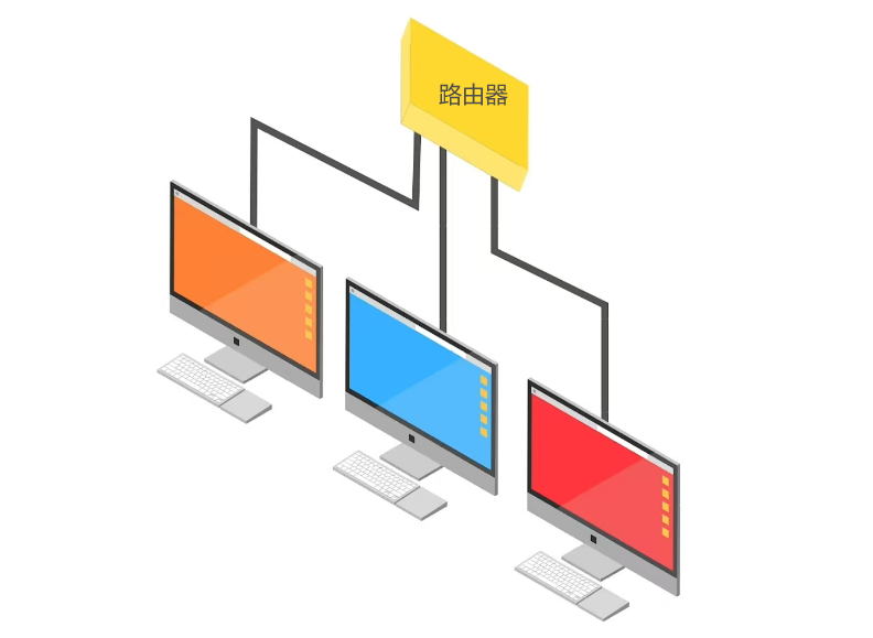
Local area networks are familiar to everyone, connecting several computers to a router allows them to communicate with each other, as shown in the figure below; the CAN protocol is similar to a local area network.
1. CAN Communication Physical Signal Lines
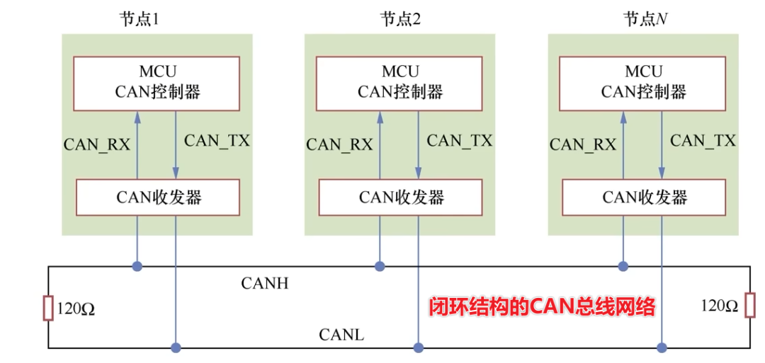
The CAN bus, as an asynchronous serial communication protocol, does not synchronize using a clock signal. It consists of two signal lines, CAN_High and CAN_Low, forming a differential signal pair for communication. The following figure illustrates the CAN communication connection: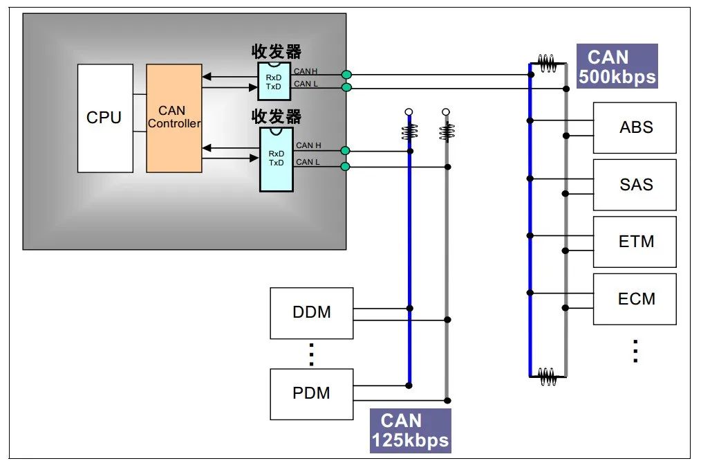 The structure of a CAN bus network can be either closed-loop or open-loop. As shown in the figure below, this is the closed-loop structure of a CAN bus network, where a 120-ohm resistor is connected at each end of the bus, forming a loop with the two signal lines. This CAN bus network is defined by the ISO 11898 standard, is high-speed, and is designed for short distances, with a communication rate ranging from 125 kbit/s to 1 Mbit/s. At a 1 Mbit/s communication rate, the maximum bus length can reach 40m.
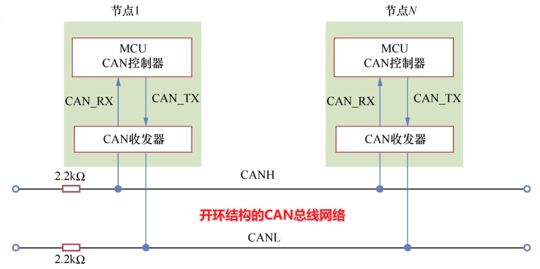
The following figure shows the open-loop structure of a CAN bus network, where the two signal lines are independent, each connected in series with a 2.2k-ohm resistor. This CAN bus network is defined by the ISO11519-2 standard, is low-speed, and is designed for long distances, with a maximum communication rate of 125 kbit/s. At a 40 kbit/s rate, the maximum bus length can reach 1000m.
2. CAN Communication Logic
To perform CAN communication, the MCU_CAN controller and CAN transceiver as shown in the figure above are required. The following example uses a common microcontroller as the MCU_CAN controller and a CAN transceiver chip as the CAN transceiver.
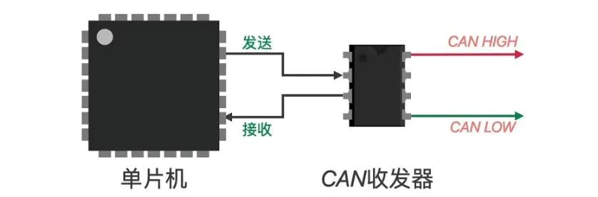
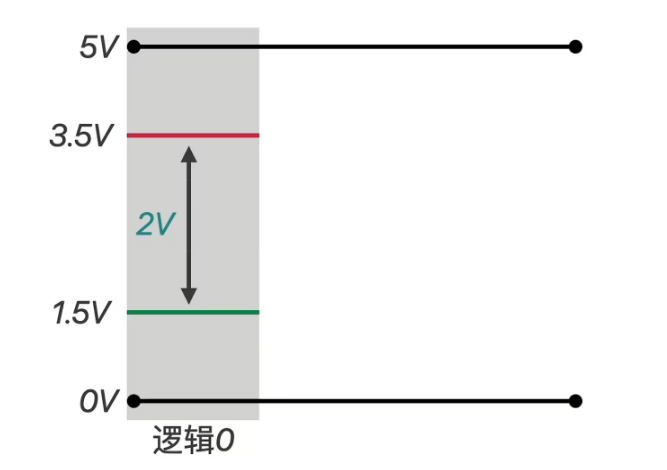
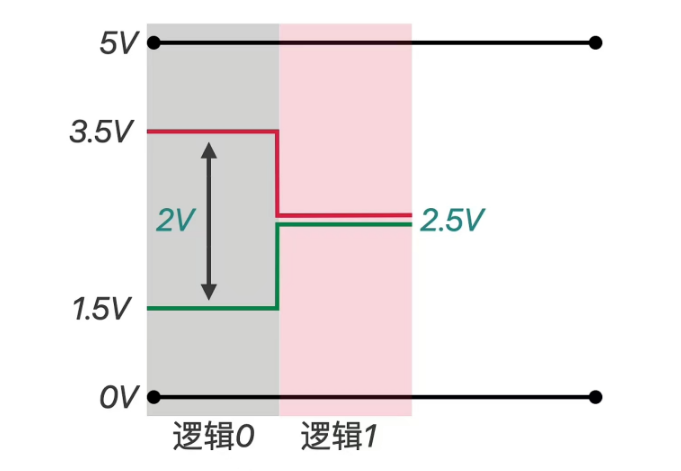
The high (logic 1) and low (logic 0) levels sent from the microcontroller’s send and receive pins are converted into differential signals by the CAN transceiver, using CAN_HIGH and CAN_LOW to represent a signal. If the microcontroller sends a low level to the CAN transceiver, the transceiver outputs one 3.5V and one 1.5V, with a voltage difference of 2V, corresponding to the dominant level of the CAN protocol, indicating logic 0;
When the microcontroller sends a high level to the CAN transceiver, both lines output a 2.5V level, resulting in a voltage difference of 0V, indicating the recessive level of the CAN protocol, logic 1.
Similarly, the CAN transceiver can convert the received differential signals back into regular high and low level signals for the microcontroller.
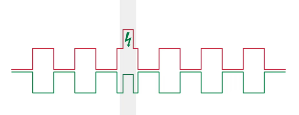
The advantages of CAN communication are also reflected in differential signal transmission. If ordinary signal transmission is used, any interference at a certain point on the signal line causing a level change would lead to transmission errors, making it difficult to use in long-distance communication or in scenarios requiring high safety;

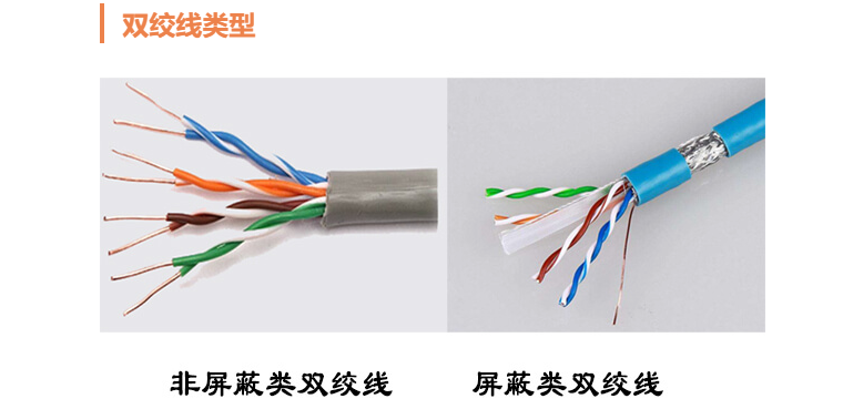
In contrast, CAN communication uses differential signals that act together, typically employing twisted pair cables, as shown in the figure below:
Thus, even if interference occurs, both signal lines are affected simultaneously, keeping the voltage difference between them unchanged, ensuring that the transmitted information remains unaffected. Therefore, CAN communication can transmit over long distances, with strong resistance to interference and effectively suppressing external electromagnetic interference.
In the CAN protocol, the differential signals represented by CAN_High and CAN_Low are specified:
Corresponding to logic 1 and logic 0, the voltage values of CAN_High and CAN_Low in open-loop and closed-loop structures differ, with the recessive and dominant levels having different voltage values. The typical voltage values of CAN bus signals under the two network structures are shown in the table below. In ISO11898, the recessive level is around 0V voltage difference, while the dominant level is mainly around 2V voltage difference. In ISO11519-2, the recessive level has a voltage difference of less than 0V, and the dominant level has a voltage difference greater than 2V.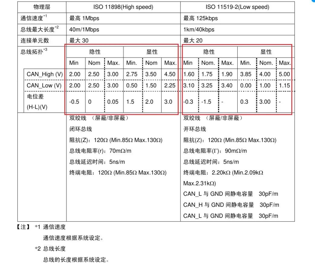 3. CAN Communication Information Content
The following figure illustrates a standard data frame of a CAN communication frame, which represents the information content transmitted via CAN communication.
3. CAN Communication Information Content
The following figure illustrates a standard data frame of a CAN communication frame, which represents the information content transmitted via CAN communication.
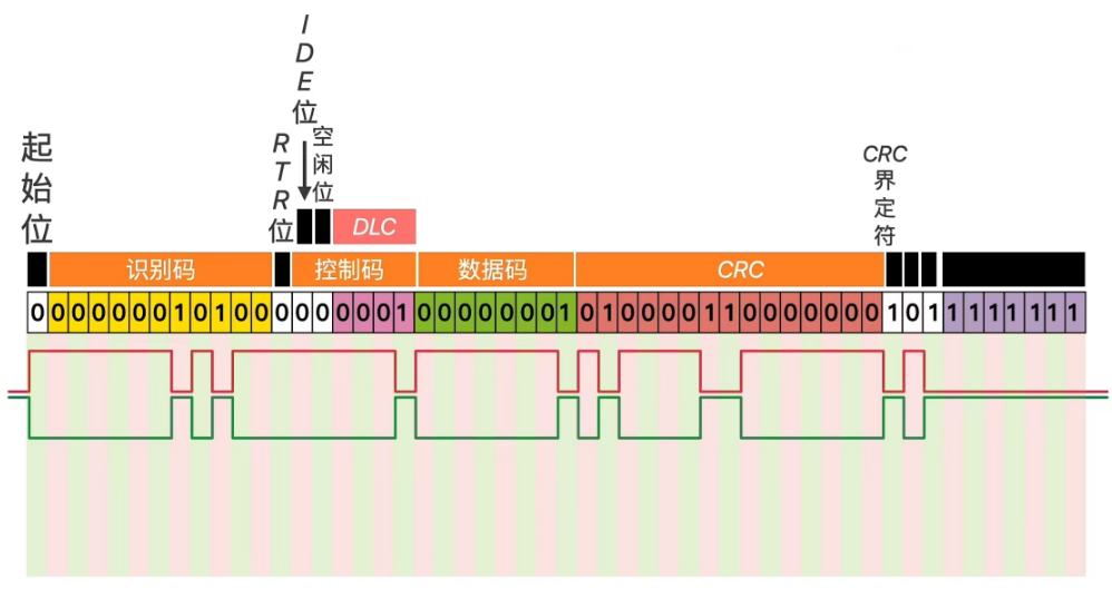
By adding a start bit, chip select (identifier) tag, and control tag at the beginning of the raw data segment, and appending a CRC delimiter, acknowledgment tag, and transmission end tag at the end of the data, these contents can be packaged in a specific format to express various signals through a single channel, similar to how various signals are transmitted on different channels in SPI, facilitating collaborative transmission.When the entire data packet is transmitted to other devices, as long as these devices interpret it according to the format, they can restore the original data. Such a message is referred to as a CAN “data frame”.
Start Bit: The SOF segment (Start Of Frame) indicates the start of the frame, which consists of a single data bit and must be a dominant level logic 0. It is used to notify each node that data will be transmitted, and other nodes synchronize through the level transition of the start frame signal.
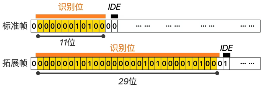
Identifier Bit: The identifier consists of 11 bits, which can determine to which node or device this frame of information is directed; each device has its own identifier.
RTR Bit: The Remote Transmission Request bit is used to distinguish between data frames and remote frames; it indicates a data frame when at a dominant level and a remote frame when at a recessive level.
Control Code: The control data length. The first bit of the control code is the IDE Bit: used to distinguish between standard format and extended format; when at a dominant level, it indicates standard format, and when at a recessive level, it indicates extended format.
After the IDE, there is a reserved idle bit, logic 0.
The last four bits are the DLC Bit: Data Length Code; when DLC is 0001, the subsequent data code is 8 bits; when DLC is 1000, the actual data code is 64 bits.
Data Code: The data segment is the core content of the data frame, which is the original information that the node intends to send.
CRC Bit: To ensure the correct transmission of data, the CAN message contains a 15-bit CRC checksum. If the CRC computed by the receiving node differs from the received CRC, it will send an error message back to the sending node, requesting it to resend the data. The CRC calculation is usually handled by the CAN controller hardware, while the handling of errors is controlled by software with a maximum retransmission count.
After the CRC checksum, there is a CRC delimiter, which is a recessive bit, primarily serving to separate the CRC checksum from the subsequent ACK segment.
ACK Segment: The ACK segment includes an ACK slot and an ACK delimiter. Similar to the I2C bus, in the ACK slot, the sending node sends a recessive bit, while the receiving node sends a dominant bit to acknowledge receipt. The ACK delimiter separates the ACK slot from the end of the frame.
EOF Segment: This segment indicates the end of the frame, consisting of 7 recessive bits sent by the sending node.
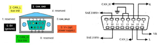
The following figure shows the CAN bus connector
4. Characteristics of CAN Communication
In SPI communication, separate signal lines exist for chip select, clock signal, data input, and data output. In contrast, CAN uses two differential signal lines to express a single signal. The simplified physical layer necessitates a more complex protocol. The key is to package data or operation commands to achieve the same or even more powerful functions.
① Multi-Master: Safety-sensitive applications (such as automotive power) require high reliability from communication systems.It is very dangerous to attribute the normal operation of the bus to a single node, and a more reasonable solution is to decentralize the bus connections, allowing each node to access the bus.This is why the CAN bus adopts a multi-master linear topology.
On the CAN bus, every node can send messages to the bus without needing to follow any preset timing; communication is event-driven. The CAN bus is only busy when new information is being transmitted, allowing nodes to access the bus very quickly. The theoretical maximum data transmission rate for the CAN bus is 1Mbps, which responds rapidly to asynchronous events, making it suitable for real-time applications at the millisecond level.
② Addressing Mechanism: Unlike other types of buses, the CAN bus does not set node addresses but distinguishes messages through identifiers.This mechanism, while increasing message complexity (adding identifiers), allows nodes to operate independently without needing to be aware of the status of other nodes.When adding nodes to the bus, attention is only required for message types, not the status of other nodes in the system.This identifier-based addressing method makes it more flexible to add nodes to the bus.
③ Bus Access CSMA/CD+AMP: The communication principle of the CAN bus can be simply described as Carrier Sense Multiple Access with Collision Detection and Arbitration based on Message Priority (CSMA/CD+AMP).CSMA (Carrier Sense Multiple Access) indicates that all nodes must wait until the bus is free before sending messages; CD+AMP (Collision Detection + Arbitration on Message Priority) means that if multiple nodes send messages to the bus simultaneously, the message with the highest priority gets the bus.
④ Carrier Sense Multiple Access: All nodes on the network are connected to the same bus in a multipoint access manner, and data transmission is broadcast. Each node must check for data transmission on the bus before sending data: if there is data on the bus, it will wait until the bus is free to send; if there is no data, it will immediately send the prepared data.
⑤ Collision Detection: When a node sends data, it continuously checks the data being sent to determine if there are any collisions with other nodes’ data; if a collision occurs, the message with the higher priority is sent first.
⑥ Non-destructive Arbitration Mechanism: Through ID arbitration, the smaller the ID number, the higher the message priority.