If you don’t want to miss my updates, remember to click the top right corner – view public account –set as starred, and send you a little star

 Source: Breadboard Community
UART is an asynchronous full-duplex serial communication protocol consisting of two data lines, Tx and Rx. Since there is no reference clock signal, both parties must agree on the baud rate, data bit width, parity bit, and stop bits configuration parameters to communicate at the same rate. Asynchronous communication transmits one character at a time, and the time interval between two characters is variable; however, the time interval between two adjacent bits within the same character is fixed. When the baud rate is 9600 bps, the time interval to transmit one bit is approximately 104.16 µs; at a baud rate of 115200 bps, it is approximately 8 µs.
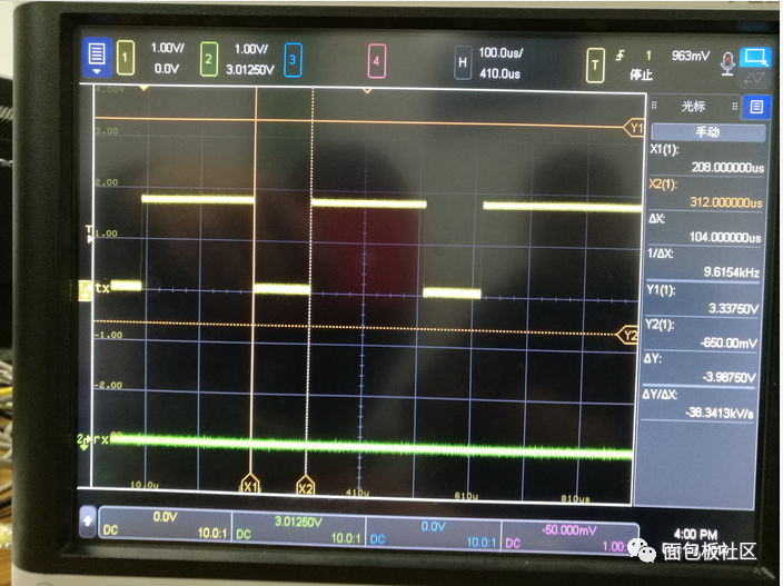
The data transmission rate is expressed in terms of baud rate, which is the number of binary bits transmitted per second. For example, if the data transmission rate is 120 characters per second, and each character consists of 10 bits (1 start bit, 7 data bits, 1 parity bit, 1 stop bit), the baud rate would be 10×120 = 1200 characters per second = 1200 baud. Data communication timing diagram: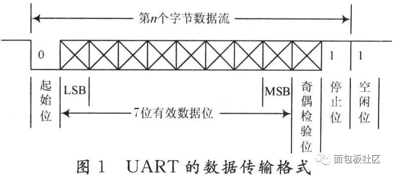 The meanings of each bit are as follows:
 Start Bit: sends a logic “0” signal first, indicating the start of the character transmission;Data Bits: can be 5 to 8 bits of logic “0” or “1”; for example, ASCII code (7 bits), extended BCD code (8 bits); little-endian transmission, meaning LSB is sent first, MSB last;Parity Bit: after adding this bit to the data bits, the number of “1” bits should be even (even parity) or odd (odd parity);Stop Bit: it is a character data end marker. It can be 1 bit, 1.5 bits, or 2 bits of high level (used for synchronization between both parties, the longer the stop bit interval, the stronger the fault tolerance);Idle Bit: in a logic “1” state, indicating that there is no data transmission on the current line;Note: Asynchronous communication is character-based. The receiving device can correctly receive data as long as it stays synchronized with the sending device within the transmission time of one character after receiving the start signal. The arrival of the next character’s start bit recalibrates the synchronization (achieved by detecting the start bit to implement self-synchronization of the clocks between sender and receiver). ↑Figure-1 Start Bit and Stop Bit
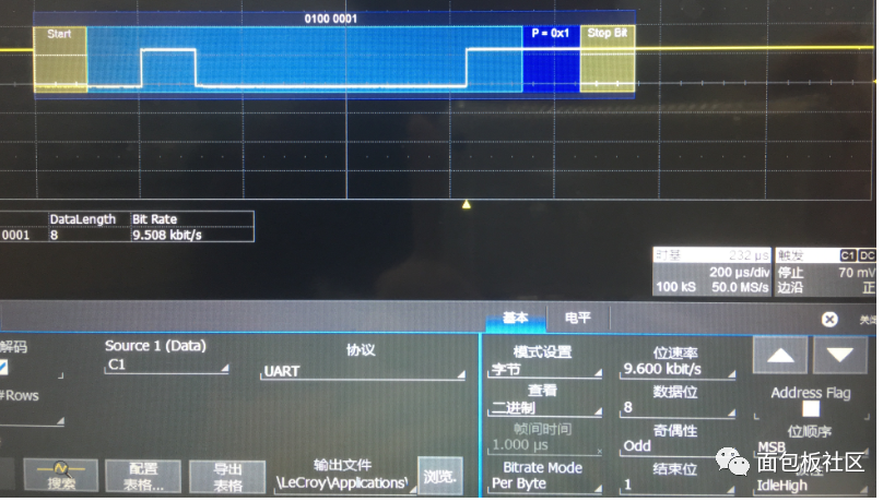 ↑Figure-2 Data Bits
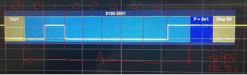 ↑Transmission of “A”The above diagram shows the waveform obtained by decoding the UART protocol for transmitting the character “A” through an oscilloscope. Based on this diagram, let’s introduce some basic parameters of UART.
 Baud Rate: This parameter is often confused with bit rate, but they are different. However, I believe that the baud rate in UART can be considered as the bit rate, meaning the number of bits transmitted per second. Common baud rates include 9600, 19200, 115200, etc. This means that this many bits are transmitted per second. Start Bit: sends a logic “0” signal first, indicating the start of data transmission. Data Bits: selectable values are 5, 6, 7, or 8, and can transmit this many bits of 0 or 1. This parameter is best set to 8, because if this value is something else when transmitting ASCII values, it will generally cause parsing issues. The reason is simple: an ASCII character value is 8 bits; if a frame’s data bits are 7, then one bit will be indeterminate, which will cause an error. Parity Bit: after adding this bit to the data bits, the number of “1” bits should be even (even parity) or odd (odd parity) to verify the correctness of data transmission. For example, when transmitting “A” (01000001): 1. For odd parity: there are two 1s in the 8 bits of the character “A”, so the parity bit must be 1 to meet the odd count of 1s (odd parity). The waveform in Figure-1 is this case. 2. For even parity: there are two 1s in the 8 bits of the character “A”, so the parity bit must be 0 to meet the even count of 1s (even parity). This bit can also be omitted, meaning no parity bit is needed. Stop Bit: it is a frame data end marker. It can be 1 bit, 1.5 bits, or 2 bits of idle level. You might find it strange that there can be 1.5 bits; indeed, it exists. Hence, when generating this UART signal, I use two waveform points to represent one bit. This doesn’t need to be delved into deeply… Idle Bit: the voltage state on the line when no data is being transmitted. It is logic 1. Transmission Direction: indicates whether data is transmitted starting from the high bit (MSB) or the low bit (LSB). For example, when transmitting “A”, if it is MSB, it is 01000001 (as shown in Figure-2); if it is LSB, it is 10000010 (as shown in Figure-4). The order of data transmission in UART is: first, a start bit is transmitted, followed by data bits, then the parity bit (which may not be needed), and finally the stop bit. This completes the transmission of one frame of data. It continues transmitting like this. Here, I also want to mention one parameter. Frame Interval: the size of the interval between frames of transmitted data can be measured in bits or time (once the baud rate is known, bits and time can be converted). For instance, after transmitting “A”, that constitutes one frame of data, and when transmitting “B”, the interval between A and B is the frame interval.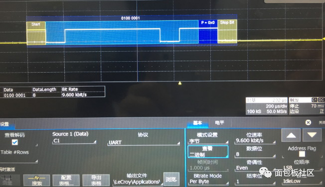 ↑Figure-3
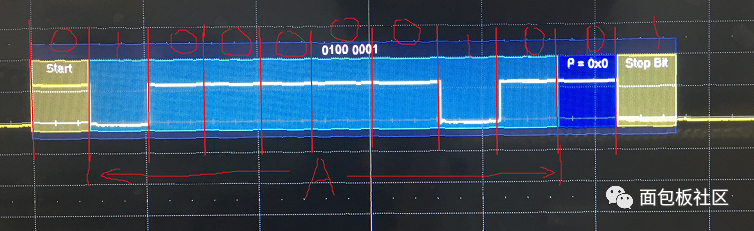 ↑Figure-4The above two figures and the below two figures transmit the same data and baud rate, but several parameters are intentionally set incorrectly to form a comparison, which helps to understand UART more deeply.

The essence of analog circuits is all here
How to measure CAN communication signals with an oscilloscope
A former colleague jumped into a central enterprise; see this treatment, this work rhythm
Disassembling the airplane black box, looking at the internal structure, PCB, and chips!