Embedded devices need to set parameters during operation, and this task is often implemented by a PC. A communication protocol must be designed for both parties, with three representative protocols as follows:
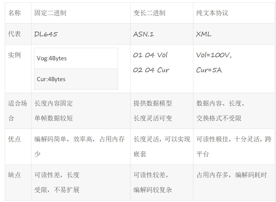
From the table above, it can be seen that the memory and computational performance of general embedded devices are limited, so fixed binary is the preferred communication protocol.
1. Simplicity
Ensure that the protocol is a simple solution; obscure and difficult-to-understand designs often lead to implementation difficulties and errors. The structure of the protocol should be flat, with each field having a clear purpose. The data fields should be designed to have fixed lengths and positions whenever possible, with detailed annotations, clear documentation, and rich examples to help users quickly get started and understand.
The protocol generally requires the following fields: frame header, length, frame type, destination address, source address, data, checksum, and frame tail.
2. Expandability
It must be ensured that the protocol can still function adequately after adding features and changing hardware in the future, which is often achieved by reserving space. Changes to the protocol should only involve quantitative increases and should not alter the structure of the protocol.
3. Low Coupling
Ideally, each protocol packet is atomic information, meaning that this protocol packet should not be linked to other protocol packets to prevent communication frame loss and errors caused by interdependencies in settings.
4. Stability
The length of the protocol packet should be appropriate: too small means it contains too little information, and a wide variety of protocol packets can easily lead to communication confusion and interdependent errors; too large means it contains too much information, resulting in poor readability, difficulty in framing and deframing, and susceptibility to communication interference. Generally, the protocol length should be measured by the minimum atomic information.
The protocol must include a verification mechanism to allow the receiver to determine whether the protocol packet has been correctly and completely received. If an error occurs, a good mechanism should be in place to ensure successful communication (e.g., retransmission).
5. High Efficiency
Differentiate protocol packet categories by information type, such as setting network information parameters or setting current operating parameters, which can be separated for easier program processing.
Coding the same type of operations into a subset is an efficient method; for example, a Read operation can be encoded as 0x0010, and a Write operation can be encoded as 0x0020.
Data should be designed as homogenous patterns whenever possible. If there are differences, at least group the same type of data together so that the program can fully utilize pointers and linear addressing to speed up processing.
6. Ease of Implementation
Try to minimize the use of complex algorithms. For example, if the communication link is stable, the checksum of the data frame can replace CRC. Unless resources are extremely tight, avoid squeezing too much information into one data packet, as this can lead to poor readability and implementation difficulties.
7. Software Development
As much as possible, let the hardware ISR complete the driver work, and avoid letting the “process” participate in complex timing logic; otherwise, the processor will be sluggish and the logic will become complicated! For example:
Receiving a fixed-length data frame can use DMA, and after receiving one frame, DMA_ISR sends a message to the process. Care should be taken to handle DMA fragmentation exceptions (where the received data frame length is normal but the data is incorrect, containing the latter half of the previous frame and the first half of the current frame).
Receiving variable-length data frames can use a state machine, sending a message to the process when “frame tail data” is received. Care should be taken to manage data disorder and timeout exceptions (when data is disordered, the state machine needs to be reset promptly, and timeouts are generally monitored using timers).
8. Consider Hardware
If the communication link is a high-speed bus (such as SPORT reaching 100Mbps), it is generally designed to generate an interrupt once per frame, implemented through length-triggered DMA, requiring the protocol to be designed for fixed lengths, as shown in Appendix A. This design has high efficiency but lower flexibility.
If the communication link is a low-speed bus (such as UART generally at 100kbps), an interrupt can be generated for each received byte, allowing the protocol to be designed for variable-length frames, as shown in Appendix B. This design has high flexibility but lower efficiency.
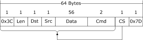
The above image shows the format of the data frame sent by the PC, with a total length of 64 bytes, which is a multiple of 4 bytes, complying with the alignment characteristics of most 32-bit processor structures.
-
0x3C: INT8U, frame header, visible character ‘<’
-
Len: INT8U, total data length of this frame, which is 64 in Figure 4
-
Dst: INT8U, identifier for the target device’s ID number
-
Src: INT8U, identifier for the source device’s ID number
-
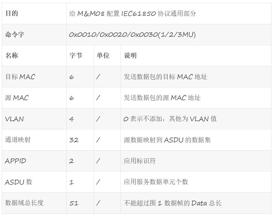
Data: 56 bytes storage area, content depends on the specific communication frame (see Table 2 for examples)
-
Cmd: INT16U, category of the data frame
-
CS: INT8U, checksum for all preceding data (62 bytes)
-
0x7D: INT8U, frame tail, visible character ‘}’
Data field data structure example:
An example of a variable-length format UART communication protocol:
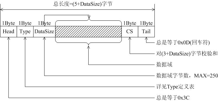
The communication frame between the PC and iWL880A (a wireless communication product, see www.rimelink.com) adopts a variable-length format, as shown in the figure below. Most devices (commonly PCs) handle receiving with the mechanism of a “carriage return” well, where the Tail in the protocol equals 0x0D (newline).
Disclaimer: This article is sourced from the internet, freely conveying knowledge, and the copyright belongs to the original author. If there are any copyright issues, please contact me for deletion.
Conclusion
This concludes this share. If you find the article good, forwarding or viewing is also our motivation to continue updating.
Related Articles:
Useful | Some Practical Operations for Nested Structures and Unions
2020 Selected Original Notes Compilation
1024G Embedded Resource Giveaway! Including but not limited to C/C++, microcontrollers, Linux, etc. Reply1024 in the public account chat interface to get it for free!