Follow+Star Public Account Number, don’t miss out on exciting content

Author | strongerHuang
WeChat Public Account | Embedded Column
In microcontroller (MCU) development, printing output is quite common and important. Today, I will share with you the common printing output methods and their differences.
1Introduction
In MCU projects, printf is mainly used to print debugging information. For example: when a program execution error occurs, it outputs relevant error messages.
Well-designed projects will generate or save log information through printed messages.
2
printf Output Methods
This tutorial mainly focuses on the printf printing output for MCUs, with common methods being:
1. UART Printing Output
2. Simulation Printing Output
3. SWO Printing Output
4. JLink-RTT Printing Output
Except for simulation, the other three methods are based on MCU hardware printing output.
In terms of printing efficiency: UART < SWO < JLink-RTT.
Each printf printing output method has different application scenarios and characteristics.
3Experimental Phenomena
First, let’s understand the content of printf through experimental phenomena, and the specific configurations will be discussed in later articles.
3.1 UART Printing Output
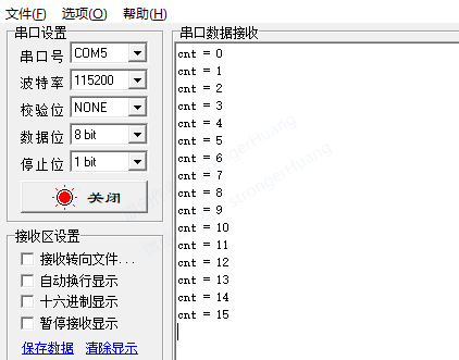
This printf is the most common way to output via UART serial port, requiring one hardware UART serial port.
3.2 Simulation Printing Output
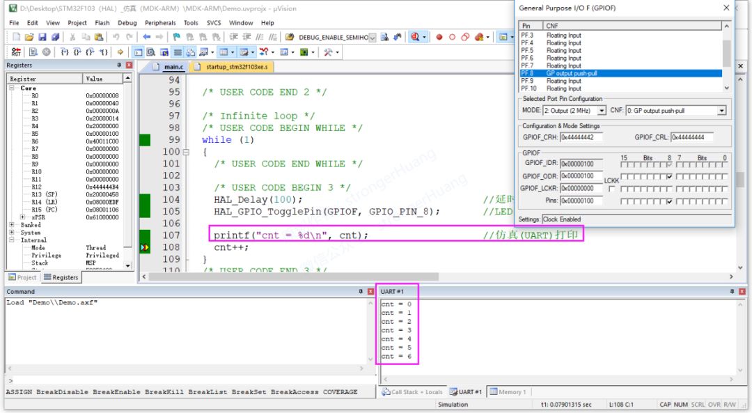
This simulates printf output in the integrated development environment without needing to connect to the development board (hardware MCU).
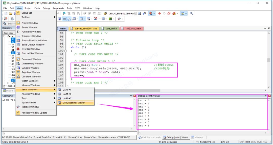
3.3 SWO Printing Output
SWO: Serial Wire Output
SWD: Serial Wire Debug
SWV: Serial Wire Viewer
SWO output requires an additional SWO (pin) line and needs to use SWV (viewer) to view the data. Here are four methods:
· Based on Keil’s ‘Debug(printf)Viewer’
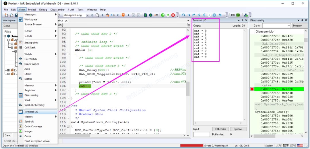
· Based on IAR’s ‘Terminal IO’
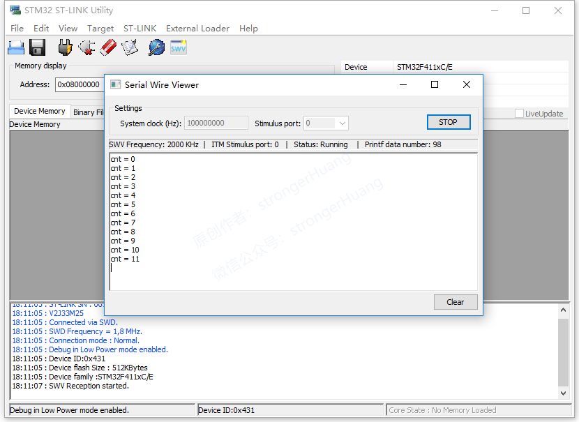
· Based on ST-LINK Utility’s ‘Serial Wire Viewer’
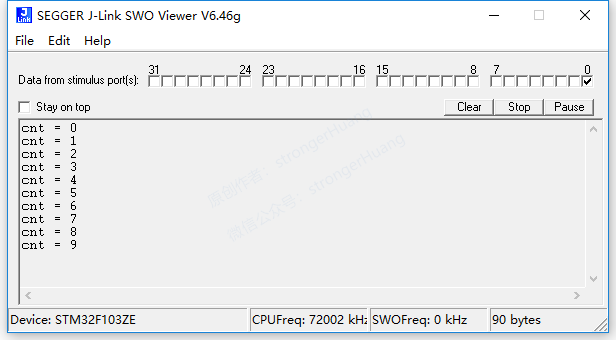
· Based on J-Link’s ‘SWO Viewer’
1. Based on Keil’s ‘Debug(printf)Viewer’
2. Based on IAR’s ‘Terminal IO’
3. Based on ST-LINK Utility’s ‘Serial Wire Viewer’
4. Based on J-Link’s ‘SWO Viewer’
Note:The first two can be viewed based on ST-Link and J-Link tools respectively, the third is viewed based on ST-Link, and the fourth is viewed based on J-Link.
3.4 JLink-RTT Printing Output
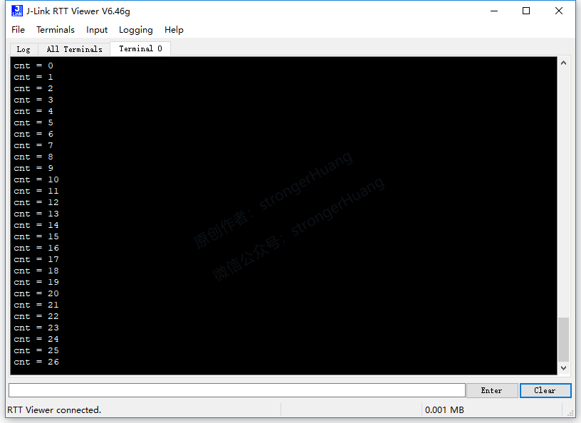
This method does not require using a UART serial port or additional SWO pins, but requires adding relevant code in the program.
4Software, Hardware Tools, and Other Notes
This tutorial uses quite a few software and tools, assuming everyone has installed and mastered the usage methods.
4.1 Software Tools
1. STM32CubeMX
Please refer to:【Column】STM32CubeMX Series Tutorial
2. Keil MDK-ARM
Please refer to:【Column】Keil MDK-ARM Series Tutorial
3. IAR EWARM
Please refer to:【Column】IAR Series Tutorial
4. STM32 ST-LINK Utility
Please refer to:【Column】ST-Link Information
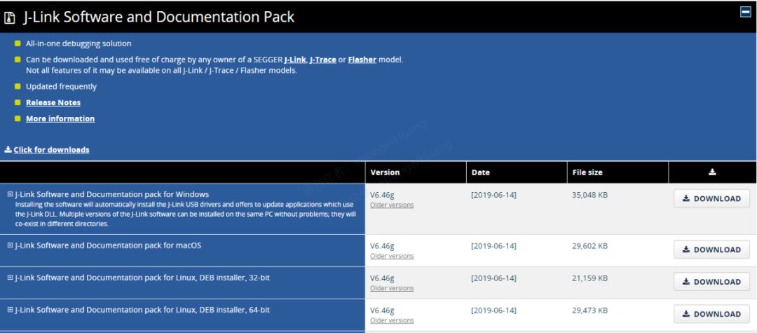
5. J-Link / J-Trace
Download link:
https://www.segger.com/downloads/jlink
4.2 Hardware
1. MCU Development Board
In principle, Cortex-M3 and M4 are both acceptable. This tutorial is based on STM32F0, F1, and F4 series.
2. Download Debugger
-
ST-Link
-
J-Link
3. PC Computer
Of course, a Windows computer is recommended, as MDK-ARM only supports Windows systems.
4.3 Other Notes
1. Source Code Project Download
To facilitate learning, this series of tutorials will provide corresponding source code projects for download. Reply with the keyword “printf” in the public account to obtain it.
2. About Simulation Output
Now development boards are very cheap (compared to before), and there may be differences between simulation and actual results, so I do not recommend software simulation.
———— END ————
Reply with ‘《Microcontroller》《printf》’ to read more related articles.
Welcome to follow my public account, reply “Join Group” to join the technical exchange group according to the rules, reply “1024” to see more content.Welcome to follow my video account:

Click “Read the Original” to see more shares, and feel free to share, bookmark, like, and view.