PCB (Printed Circuit Board), also known as printed circuit board in Chinese, is an important electronic component and the support for electronic components. Since it is made using electronic printing technology, it is called a “printed” circuit board.
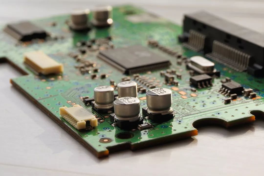
Before the advent of PCBs, circuits were composed of point-to-point wiring. This method had low reliability because as the circuit aged, broken wires could lead to open or short circuits. Wiring technology was a significant advancement in circuit technology, improving the durability and replaceability of connections by wrapping small diameter wires around the pillars of connection points.
As the electronics industry transitioned from vacuum tubes and relays to silicon semiconductors and integrated circuits, the size and cost of electronic components decreased. Electronic products began to appear more frequently in the consumer sector, prompting manufacturers to seek smaller and more cost-effective solutions. Thus, PCBs were born.
PCB Manufacturing Process
The PCB manufacturing process is quite complex. Taking a four-layer printed circuit board as an example, the main steps include PCB layout, core board production, inner layer PCB layout transfer, core board drilling and inspection, lamination, drilling, copper chemical deposition on hole walls, outer layer PCB layout transfer, and outer layer PCB etching.
1. PCB Layout
The first step in PCB manufacturing is to organize and check the PCB layout. The PCB manufacturing factory receives CAD files from the PCB design company. Since each CAD software has its unique file format, the PCB factory converts it into a unified format—Extended Gerber RS-274X or Gerber X2. Then, the factory engineers check whether the PCB layout meets manufacturing standards and if there are any defects.
2. Core Board Production
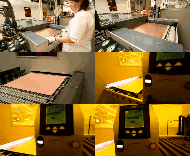
Clean the copper-clad board, as any dust could lead to short circuits or open circuits in the final product.
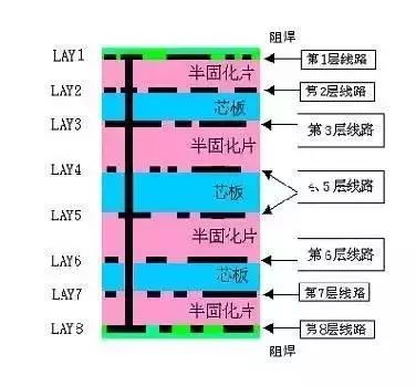
The image below shows an 8-layer PCB, which is actually made up of 3 copper-clad boards (core boards) and 2 copper films, bonded together with prepreg. The production sequence starts from the innermost core board (layers 4 and 5), stacking continuously and then securing them. The production of a 4-layer PCB is similar, but only uses 1 core board and 2 copper films.
3. Inner Layer PCB Layout Transfer
First, the two layers of circuits on the innermost core board must be produced. After cleaning the copper-clad board, a photosensitive film is applied to its surface. This film solidifies when exposed to light, forming a protective layer on the copper foil of the copper-clad board.
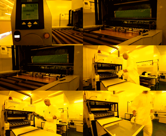
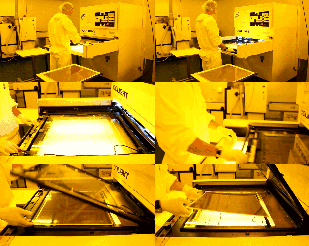
Two layers of PCB layout film and double-layer copper-clad boards are then inserted with the upper layer PCB layout film to ensure the precise alignment of the two layers of PCB layout films.
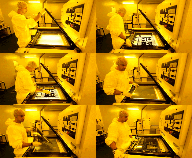
The UV lamp of the exposure machine irradiates the photosensitive film on the copper foil. Under the transparent film, the photosensitive film solidifies, while the film that is not exposed to light remains uncured. The copper foil beneath the solidified photosensitive film represents the required PCB layout, functioning similarly to the ink of a laser printer for manual PCBs.
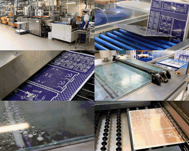
Then, an alkaline solution is used to wash away the uncured photosensitive film, leaving the required copper foil circuit covered by the solidified photosensitive film.
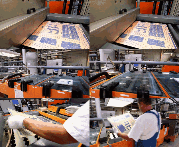
Next, a strong alkali, such as NaOH, is used to etch away the unnecessary copper foil.
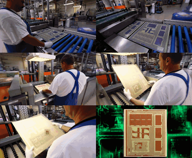
The solidified photosensitive film is then peeled off, revealing the required PCB layout circuit copper foil.
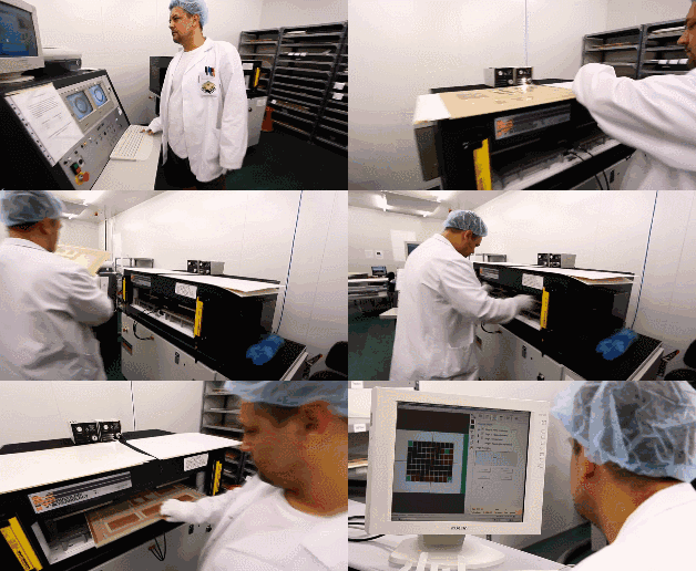
4. Core Board Drilling and Inspection
The core board has been successfully produced. Next, positioning holes are drilled into the core board to facilitate alignment with other materials in the subsequent steps.
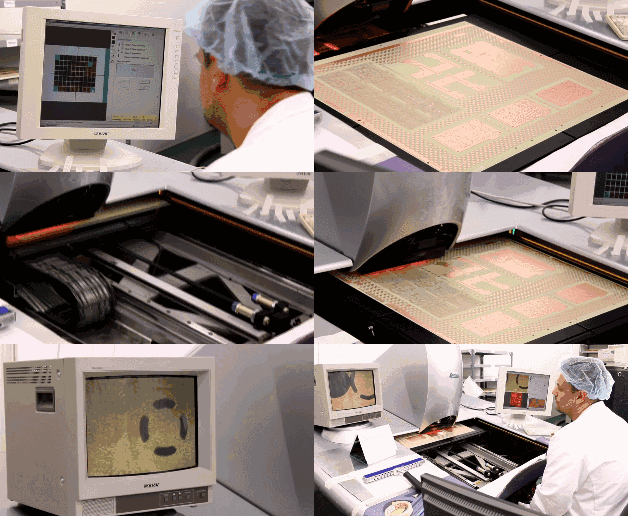
Once the core board is pressed together with other layers of PCB, modifications cannot be made, making inspection very important. Machines will automatically compare the core board with the PCB layout drawings to check for errors.
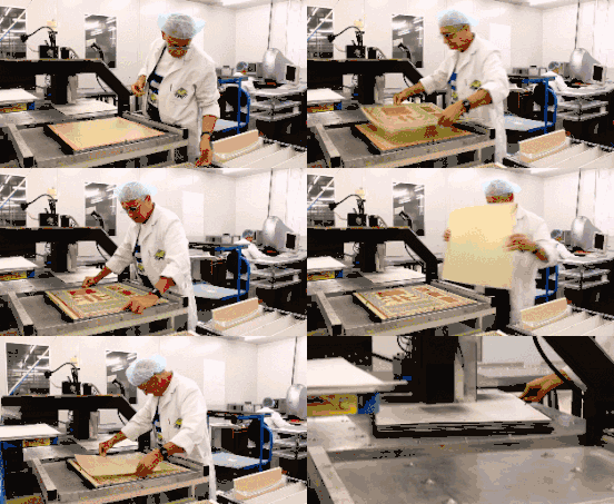
5. Lamination
A new material called prepreg is required here, which serves as an adhesive between core boards (when PCB layers > 4) and between the core board and outer copper foil, while also providing insulation.
The lower copper foil and two layers of prepreg have been pre-aligned and fixed in place using the positioning holes, and the prepared core board is placed in the positioning holes. Finally, two layers of prepreg, one layer of copper foil, and one layer of pressure-bearing aluminum plate are sequentially placed over the core board.
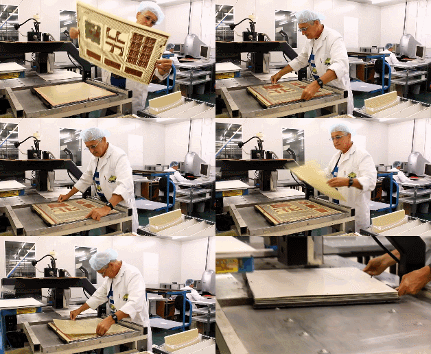
The PCB boards clamped by the aluminum plates are placed on a rack and sent into a vacuum hot press for lamination. The high temperature in the vacuum hot press melts the epoxy resin in the prepreg, fixing the core boards and copper foils together under pressure.
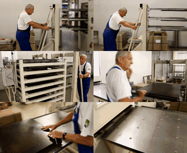
After lamination is completed, the upper aluminum plate used to press the PCB is removed. The pressure-bearing aluminum plate is also taken away, serving to isolate different PCBs and ensure the smoothness of the outer copper foil of the PCB. At this point, the PCB taken out will be covered on both sides with a layer of smooth copper foil.
6. Drilling
To connect the four layers of isolated copper foils within the PCB, through holes must first be drilled to penetrate the PCB, and then the hole walls must be metalized for conductivity.
The X-ray drilling machine locates the inner core board, automatically finding and positioning the hole locations on the core board, then making positioning holes on the PCB to ensure that the drilling will pass through the center of the hole.
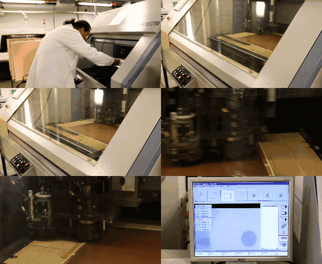
An aluminum plate is placed on the drilling machine, and the PCB is placed on top. To improve efficiency, 1 to 3 identical PCBs may be stacked together for drilling, depending on the number of layers in the PCB.
Finally, an aluminum plate is placed on top of the uppermost PCB to prevent tearing of the copper foil on the PCB when the drill bit enters and exits.
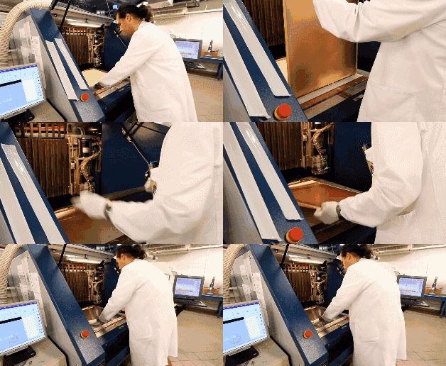
During the previous lamination process, the melted epoxy resin was squeezed out of the PCB, so it needs to be trimmed. The template milling machine cuts around the PCB according to the correct XY coordinates.
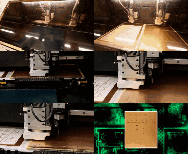
7. Copper Chemical Deposition on Hole Walls
Since almost all PCB designs use through holes to connect different layers of circuits, a good connection requires a 25-micron copper film on the hole walls. This thickness of copper film must be achieved through electroplating, but the hole walls are made of non-conductive epoxy resin and glass fiber board.
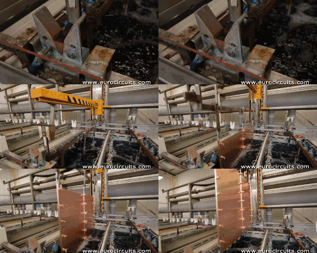
So the first step is to build up a layer of conductive material on the hole walls, forming a 1-micron copper film on the entire PCB surface, including the hole walls, through chemical deposition. The entire process, including chemical treatment and cleaning, is controlled by machines.
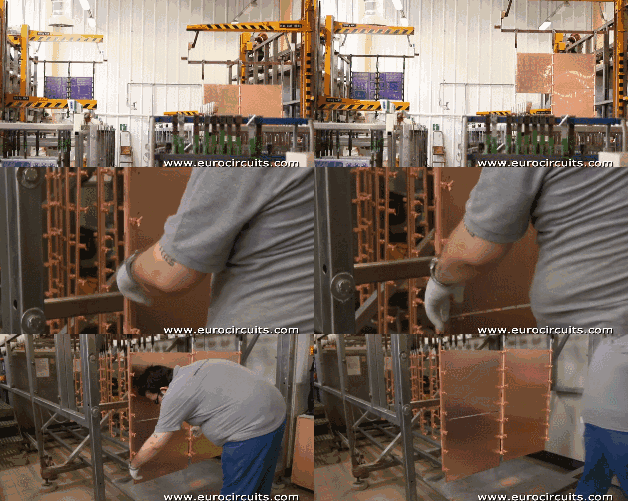
Securing the PCB
Cleaning the PCB
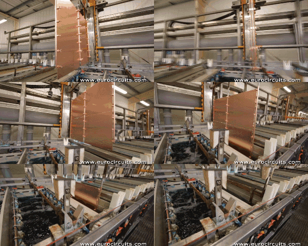
Shipping the PCB
8. Outer Layer PCB Layout Transfer
Next, the outer layer PCB layout is transferred to the copper foil. The process is similar to the previous inner layer core board PCB layout transfer, both using photocopied films and photosensitive films to transfer the PCB layout to the copper foil, with the only difference being that positive film is used for the outer layer.
The inner layer PCB layout transfer uses a reduction method with negative film. The solidified photosensitive film on the PCB represents the circuit, while the uncured photosensitive film is washed away, and the exposed copper foil is etched, leaving the PCB layout circuit protected by the solidified photosensitive film.
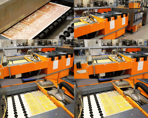
The outer layer PCB layout transfer uses a normal method with positive film. The solidified photosensitive film on the PCB covers the non-circuit area. After washing away the uncured photosensitive film, electroplating is performed. Areas with film cannot be electroplated, while areas without film are first plated with copper and then with tin. After stripping the film, alkaline etching is performed, and finally, the tin is removed. The circuit pattern is left on the board due to the protection of the tin.
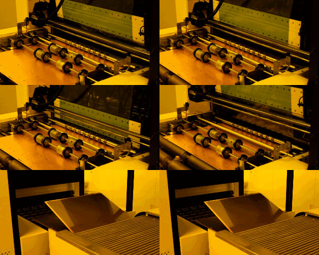
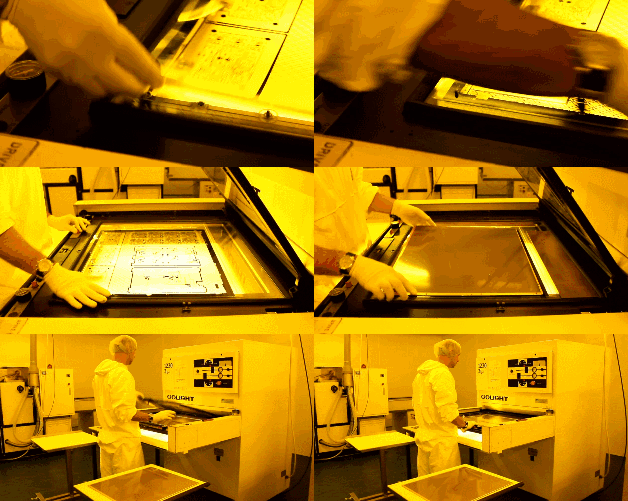
The PCB is clamped with clips while the copper is electroplated. As mentioned earlier, to ensure good conductivity at the hole locations, the copper film electroplated on the hole walls must have a thickness of 25 microns, so the entire system will be automatically controlled by a computer to ensure precision.
9. Outer Layer PCB Etching
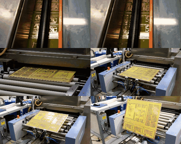
Next, a complete automated production line completes the etching process. First, the solidified photosensitive film on the PCB board is washed away. Then, a strong alkali is used to remove the unnecessary copper foil covered by it. After cleaning, the 4-layer PCB layout is completed.
Copyright Notice: This article is copyrighted by the original author and does not represent the views of the association. Articles promoted by the “Jiangxi Province Electronic Circuit Industry Association” are for sharing purposes only and do not represent the stance of this account. If there are copyright issues, please contact us for removal.