
The goal of this design is to produce an isolated DAC output. It requires a 12V power supply to generate an output of 0~5V, achieving approximately 13.3 bits of resolution at 10,000 counts. The DAC output must stabilize within 1 second after changing settings, and it should maintain stability and low noise over extended periods. The only DACs that meet these requirements are those with a resolution of 14 bits or higher, which are relatively expensive. Typically, these use I2C or SPI interfaces, and achieving isolation requires multiple channels. For I2C interfaces, achieving bidirectional isolation of the data line is also challenging. Therefore, we consider directly using a microcontroller’s PWM output, combined with opto-isolation and filtering. As shown in the diagram, the PWM signal directly drives the diode of the opto-isolator. When PWM is high, the TL431 is powered, generating a 2.5V output. When PWM is low, the output is pulled down to ground. This 2.5V PWM signal is amplified by a factor of two and then passed through a third-order filter. The cutoff frequency of the filter is approximately 24Hz.
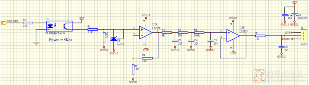 During actual testing, it was found that the output voltage was slightly higher than the voltage calculated from the PWM duty cycle.
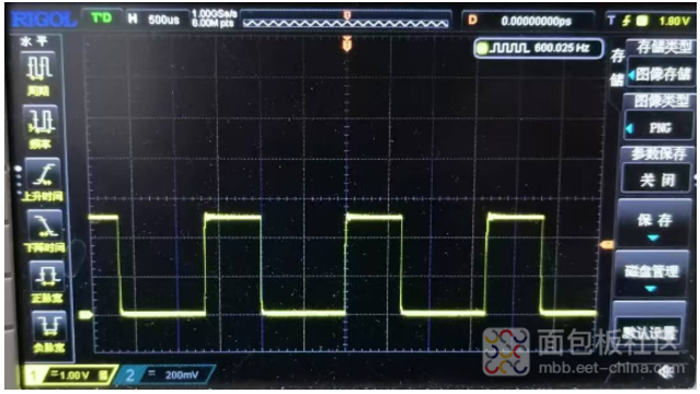 The reason is that the first stage LM358 cannot produce an output low enough to reach zero.
 We attempted to modify the circuit so that the TL431 output signal is filtered before amplification.
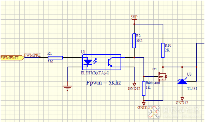
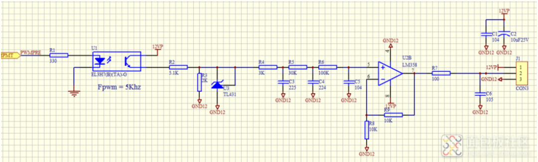 As a result, when PWM is low, the output signal source resistance increased, making it impossible to pull down completely. The output still remained high. We changed the PWM source to the following structure, using a MOSFET to short to ground when low. The signal source was improved. However, the circuit directly outputs 5V upon power-up, which clearly does not meet the design requirements.
 If we replace the operational amplifier with a rail-to-rail output type, it may improve the situation. However, it still cannot reach zero.
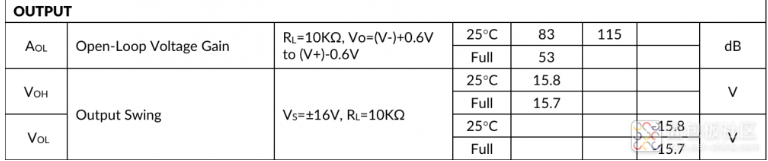 Additionally, we also tried using a PWM DAC chip.
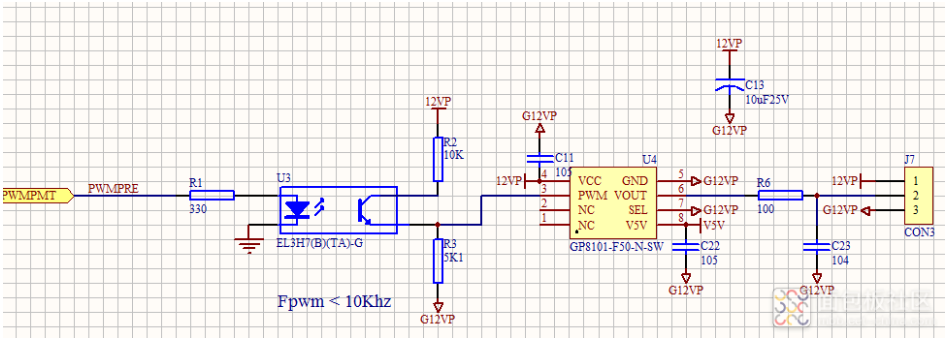 The accuracy still has some deviation, but it is slightly less. The noise is somewhat higher.Author: southcreek, Source: Breadboard Community