CANopen to Modbus Slave – HD67002 Gateway Converter
Author: Zou Wuyi Mobile185-020-77899 Email[email protected]
1、Product Features:The configurable CANopen Modbus RTU Slave Converter has the following features:
- Realizes bidirectional information exchange between CANopen network and ModBUS network;
- Provides electrical isolation between the two buses;
- Allows writing to SDO (Service Data Object) via ModBUS words;
- Allows reading of SDO via ModBUS words;
- Allows reading of EMCY (Emergency Message) via ModBUS words;
- Allows reading of PDO (Process Data Object) via ModBUS words;
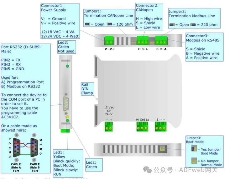
- The communication interface is serial RS232/485;
- The operating temperature range is -40°C to 85°C.
This gateway can be configured with up to 1600 SDOs.The maximum number of the following items (EMCY, EMCY words, PDO, stored PDO) depends on the available memory of the gateway and the defined SDO count.
2、Gateway Configuration: The “Gateway CANopen to Modbus” allows communication between CANopen network and Modbus network.You need to install Compositor SW67002 software on your PC to perform the following operations:
- Define SDO (Service Data Object) of CANopen that can be accessed from Modbus;
- Define how to update SDO in CANopen from Modbus;
- Define EMCY (Emergency Message) of CANopen that can be accessed from Modbus;
- Define how and which EMCY generated in CANopen can be filtered;
- Define which and how PDO (Process Data Object) of CANopen can be accessed from Modbus;
- Update the new configuration of the device;
3、New Project / Open Project: The “New Project” button creates a folder containing the entire device configuration.The device configuration can also be imported and exported:
- To clone the programmable CANopen to Modbus gateway configuration to configure another device in the same way, the folder and all its contents must be retained;
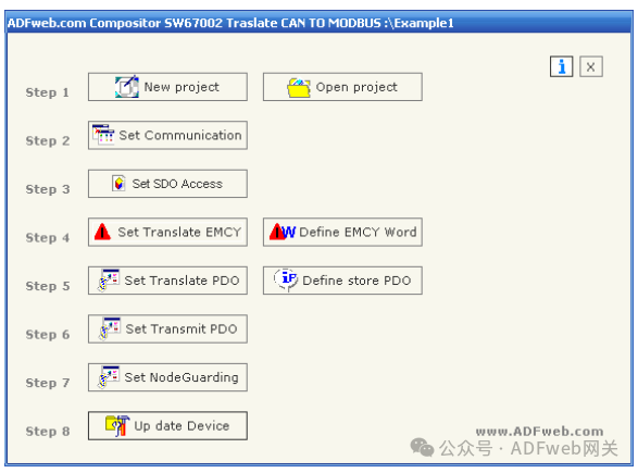
- To clone a project for a different version of that project, simply copy the project folder and rename it, then use the “Open Project” button to open the new folder. When creating a new project or opening an existing project, you will have access to various configuration sections of the software:
- “Set Communication”;
- “Set SDO Access”;
- “Set Conversion EMCY“: otherwise define EMCY words;
- “Set Conversion PDO“: otherwise define stored PDO .
4、Communication Settings:
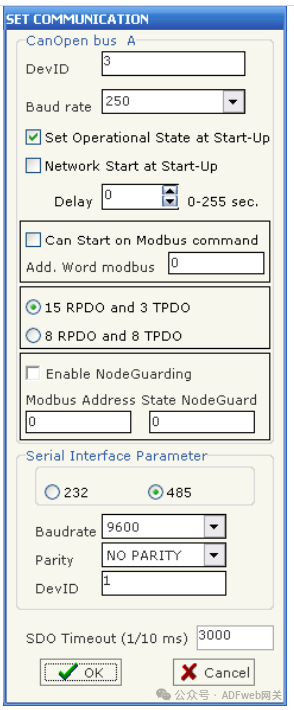
This section defines the basic communication parameters of the two buses (CANopen and Modbus). Through the main interface (Figure 4), the “Set Communication” button in SW67002 opens the “Set Communication” window (Figure 5):
- In the “DevID” field, define the corresponding CANopen and Modbus gateway addresses;
- In the “Baud Rate” field, define the communication rate of the two buses;
- The checkbox “Set Run State on Startup” is used to set the device’s run state when the device starts;
- The checkbox “Network Start on Startup” is used to send a run command to the CANopen network when the device starts (i.e., when the device starts, send a command to the Modbus network to make all devices enter the run state);
- In the “Delay” field, define the delay time before sending network commands to CANopen;
- The checkbox “Start CAN via Modbus Command” is used to send Modbus commands (send words) to one or all devices in the CAN network to set the run/ pre-run state.
- The high byte value of the sent word is:
- 1 indicates run state;
- 2 indicates pre-run state.
- The low byte of the sent word must be the address of the device to be operated (run/ pre-run).
- Example: If you want to set the CANopen device with address 3 to run state, you must enter “259” in the “Modbus Additional Word” field.
Note:257=0x01.11.If set to 0 in the “Modbus Additional Word” field, this operation will apply to all devices.
- The gateway has two optional PDO configurations:15RPDO and 3RPDO or 8RPDO and 8TPDO. Choose the desired option;
- The gateway has two optional output interfaces on the Modbus side:RS485 or RS232. Choose the desired option;
- In the “Parity” field, define the parity method for serial communication;
- “SDO Timeout” is the maximum time the device waits for a response from the queried slave;
- Data bits and stop bits are serial parameters, defaulting to 8 data bits and 1 stop bit.
5、Set SDO Access:
“Set SDO Access” Section
In the “Set SDO Access” section, the following objects can be defined:
- One SDO of CANopen can be accessed from one word of ModBUS;
- One SDO of CANopen can be accessed from which word of ModBUS.
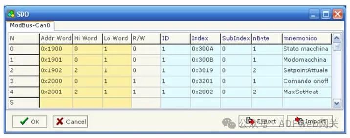
By pressing the “Set SDO Access” button in the SW67002 main window (Figure 4), the “SDO” window (Figure6) will appear.
The meanings of the listed data are as follows:
- In the “Address Word” field, enter the address of the SDO that supports ModBUS words;
- In the “High Byte” field, enter the correspondence between the high byte of the ModBUS word and the SDO byte (Note: its numbering can be 0, 1, 2, 3, 4)
- 1 = first byte of SDO;
- 2 = second byte of SDO;
- 3 = third byte of SDO;
- 4 = fourth byte of SDO;
- 0 = no byte.
- In the “Low Byte” field, enter the correspondence between the low byte of the ModBUS word and the SDO byte (Note: its numbering can be 0, 1, 2, 3, 4)
- 1 = first byte of SDO;
- 2 = second byte of SDO;
- 3 = third byte of SDO;
- 4 = fourth byte of SDO;
- 0 = no byte.
- In the “Read/Write” field, if SDO is only for reading, enter the number “0“; if SDO can also be used for writing, enter the number “1“;
- In the “ID” field, enter the address of the CANopen device;
- In the “Index” and “Subindex” fields, these are the coordinates of SDO in CANopen;
- In the “Byte Count” field, indicate the length of SDO;
- In the “Mnemonic” field, a brief description can be inserted.