Supported baud rate range: 9600—-12M
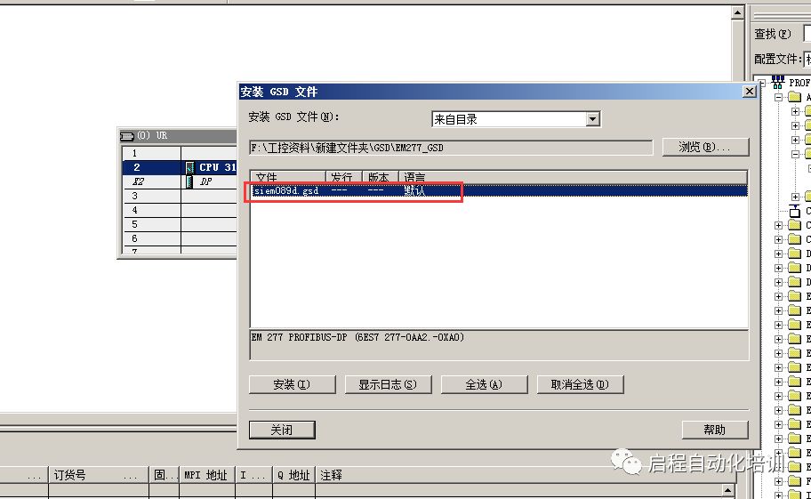
Order number: 6ES7-277-0AA22-0XA0
1. First, install the GSD file for EM277 (GSD file download link: http://www.con-star.com/download/download11.html)

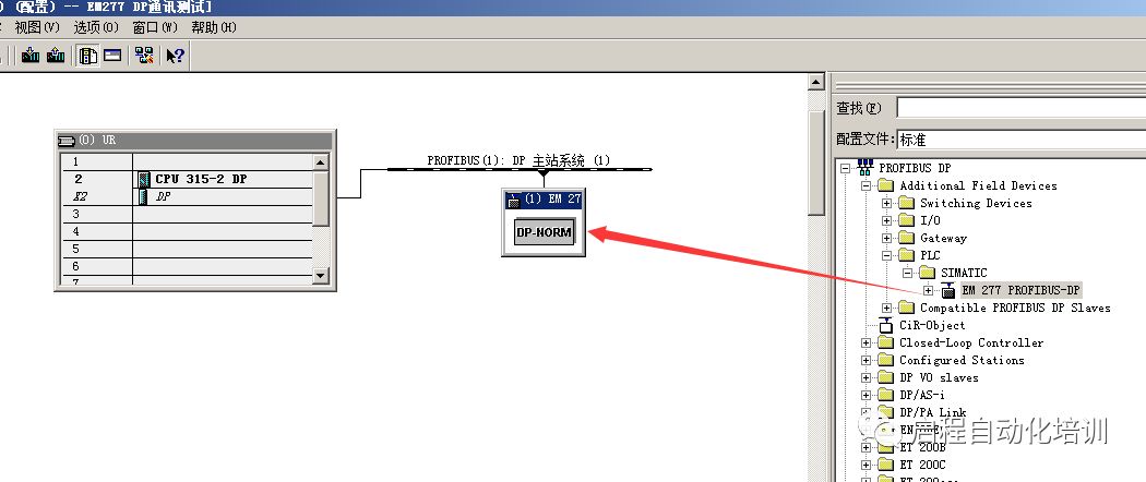
2. In the path PROFIBUS DP—Additional Field Devices—PLC—SIMATIC—EM277, drag it into the DP line configuration
3. Click on “EM277 profibus dp” to see various types of communication data classifications, such as “2 BYTE OUT/ 2 BYTE IN” for 2 bytes input and 2 bytes output
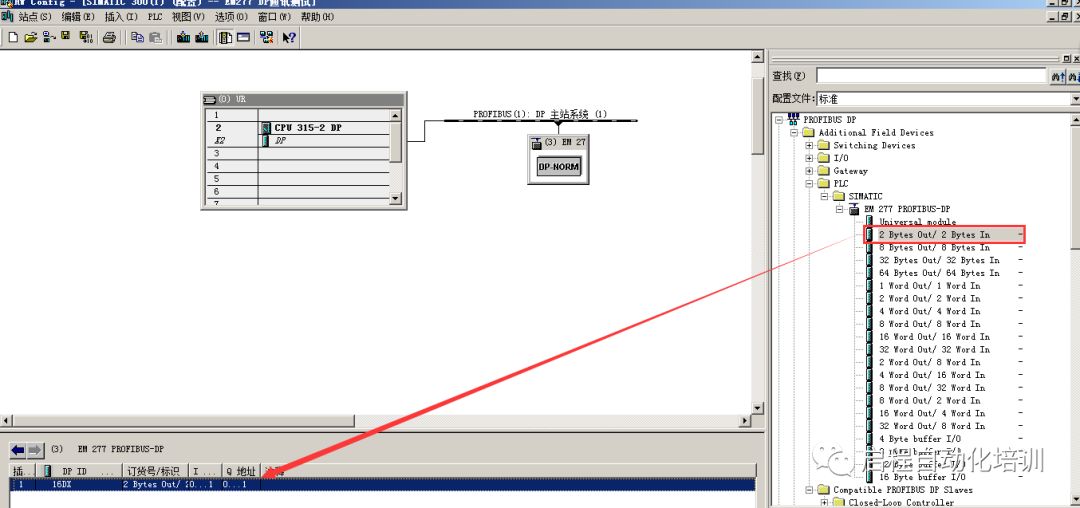
The corresponding two bytes are IB0-IB1 and QB0-QB1
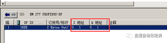
You can double-click the option bar to set it
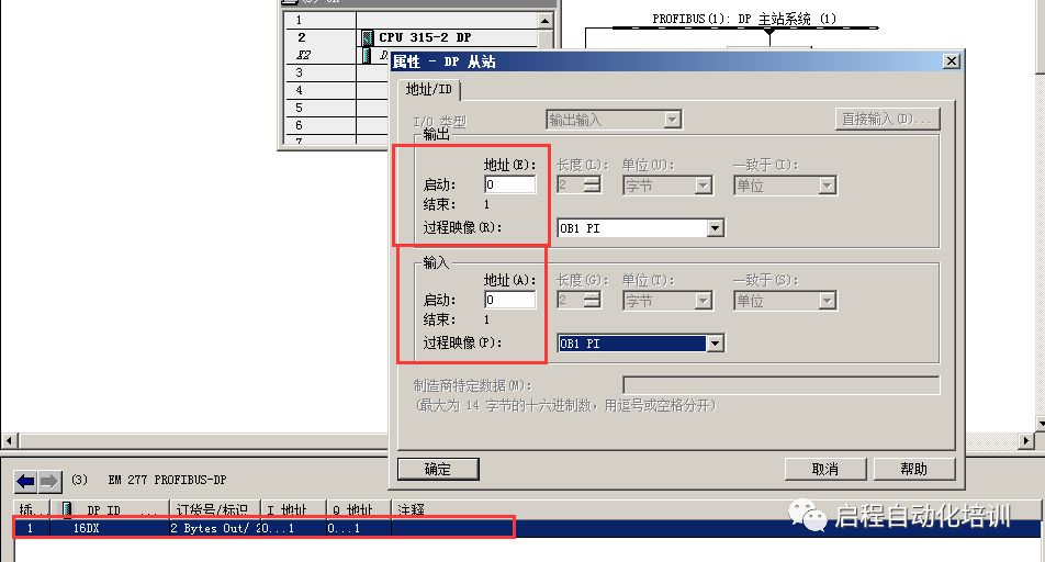
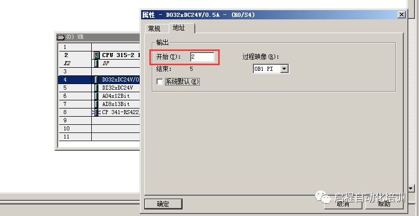
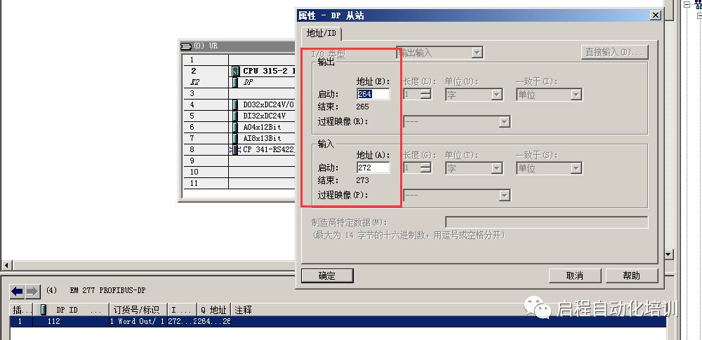
4. Set the DP communication addresses for the master and slave stations
The master station address is 2, and the slave station address is 4
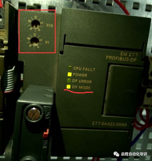
The EM277 sets the DP slave address by rotating the rotary switch in the upper left corner of the module. For a slave address of “4”, rotate the arrow in the X10 position to “0” and the arrow in the X1 position to “4”; if the slave address is “25”, rotate the arrow in the X10 position to “2” and the arrow in the X1 position to “5”
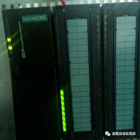
If communication is normal, the green light of the DX MODE on the EM277 module is on, and the master CPU indicator is normal; if there is a communication error, the DX MODE light is off, and the master CPU indicator reports a fault, and the CPU cannot start.
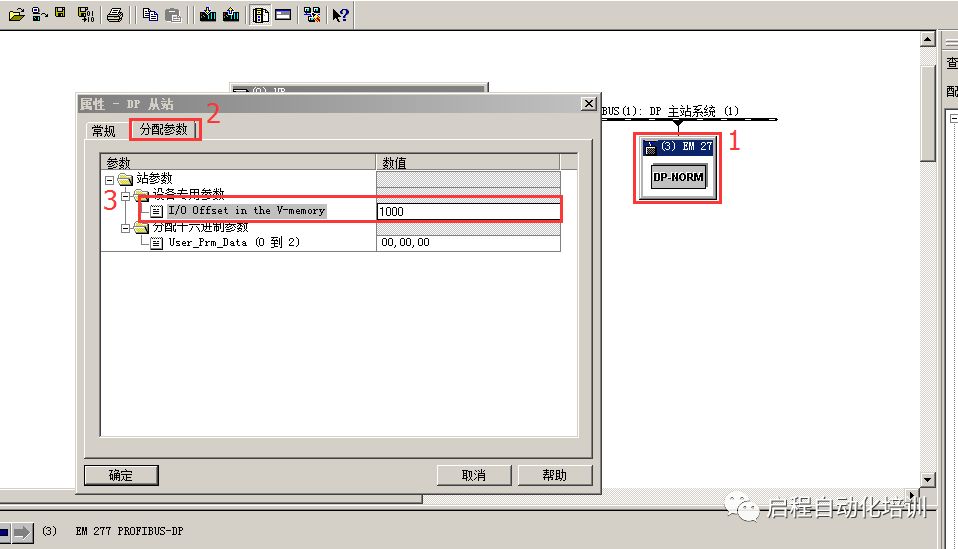
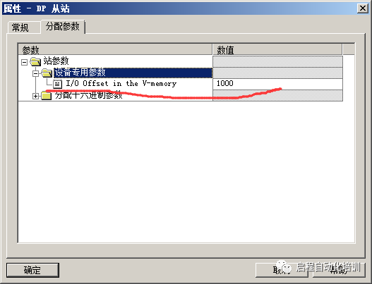
5. Double-click EM277—-Assign parameters—-I/O offset in the V-memory
Set the corresponding VB storage area value for the S7-200 slave. The value filled in corresponds to that amount
For example, the setting is VB1000 as the mapping starting address
Indicates: QB0-QB1——VB1000-VB1001
IB0-IB1——VB1002-VB1003
6. Assign addresses to the DI DO module. Since the previous step has occupied the addresses IB0, IB1, QB0, and QB1, the starting address in the module can only start from IB2 and QB2
7. Write the program
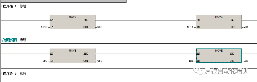
S7-300 master station program
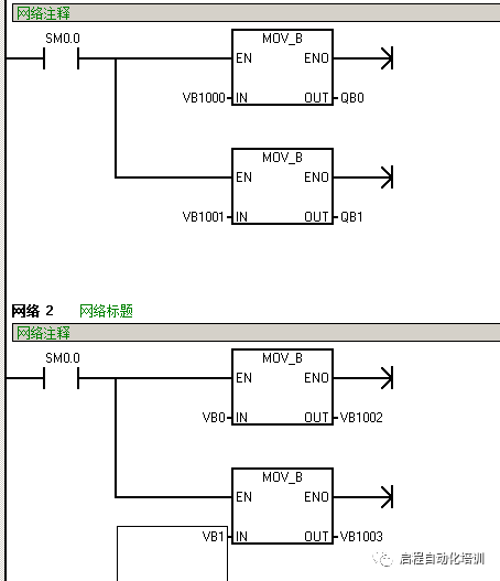
S7-200 slave station program
Data flow direction:
MB10 (S7-300)——QB0 (S7-300)——-(DP communication)——VB1000 (S7-200)—-QB0 (S7-200, actual output)
VB0 (S7-200)——-VB1002(S7-200)——–(DP communication)——–IB0 (S7-300)——QB2(S7-300 actual output)
Test 1:
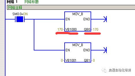
In STEP7, write “170” to MB10 and then transfer it to QB0 (S7-300) using the MOVE instruction, which is then sent to S7-200 via DP communication
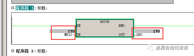
Monitor Micro/WIN, VB1000 has moved the data “170” to QB0 (S7-200)
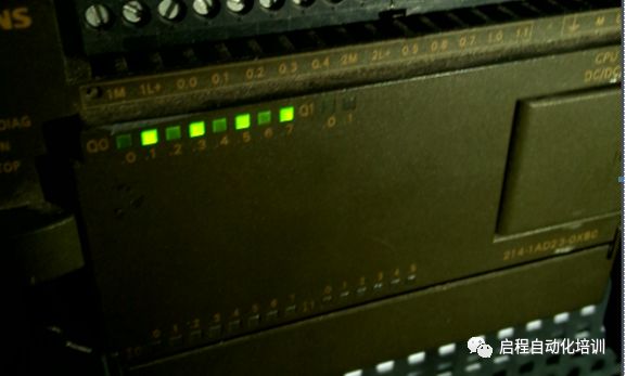
Actual PLC photo: 170 (10#) == 10101010 (2#)
Test 2:
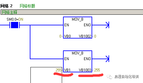
In Micro/WIN, write “255” to VB1 and transfer it to VB1003 using the MOVE instruction, then send it to IB1 (S7-300) via DP communication
Monitor STEP7, IB1 value is “255” and then transfer it to QB3 (S7-300) for actual output
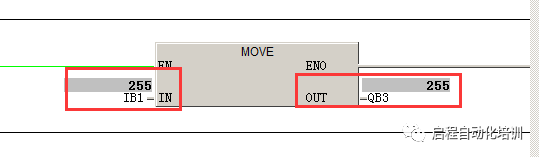
Actual PLC photo
Additional: Analog Quantity Testing
Just change the following operations:
1. In configuration, select a word type transmission method, such as 1Word Out/ 1Word In for one word type output and one word type input
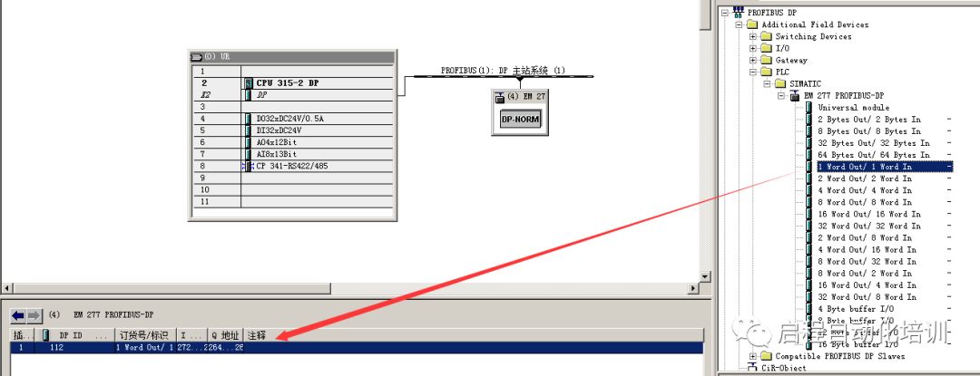
Then set the DP slave’s output and input addresses, such as: output PQW264 and input PIW272
2. The mapping address is still the V storage area, with 1000 as the starting address
PQW264——VW1000
PIW272——VW10002
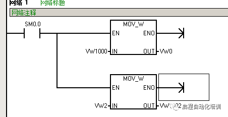
3. Write the program
S7-300
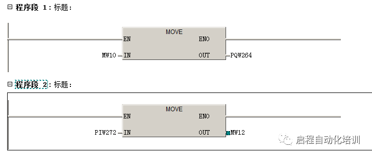
S7-200
Data transmission
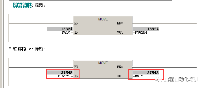
MW10(S7-300)—PQW264(S7-300)—(DP communication)—VW1000(S7-200)—VW0(S7-200)
VW2(S7-200)—VW1002(S7-200)—(DP communication)—PIW272(S7-300)—MW12(S7-300)
5. Test 1
In STEP7, write “13824” to MW10
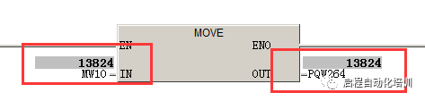
Monitor Micro/WIN, the value of VW1000 has changed to “13824”
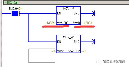
Test 2
In Micro/WIN, write “27648” to VW2 and MOVE it to VW1002
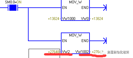
Monitor STEP7, the value of PIW272 has changed to “27648”
Reprinting is a form of motivation, sharing is a virtue
Previous reviews
How do ABB robots communicate with vision?
27 Differences Between Stepper Motors and Servo Motors
100 Classic Questions and Answers from Beginner to Master of S7-300 (Part 1)
100 Classic Questions and Answers from Beginner to Master of S7-300 (Part 2)
Essential Knowledge for Automation Engineers [Case Analysis]
About Us: Qicheng Automation Training, China’s leading industrial robot training service provider
Contact Number:0755-33160627 13809869603
Training Projects:Robots + PLC System Integration + Motion Control + Robots + Machine Vision
Special Services:3000 square meters training center + job recommendation + industry-leading curriculum system

+ Teacher WeChat, learn about class details