Table of Contents
1 Overview of CAN
1.1 What is CAN
1.2 History of CAN
1.3 CiA Organization
1.4 OSI Model of CAN
1.5 Characteristics of CAN
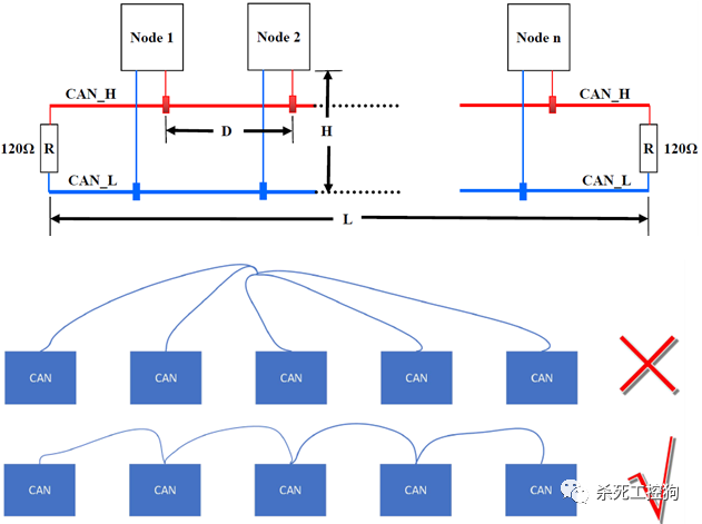
1.6 Topology of CAN
1.7 Data Frame of CAN
1.8 Common CAN Application Layer Protocols
2 Overview of CANopen
2.1 What is CANopen
2.2 CANopen Network Model
2.3 Common Standards of CANopen
2.4 CANopen Object Dictionary
2.5 CANopen Communication Identifiers
3 Overview of CANopen Protocol
3.1 Common Terms
3.2 Communication State Machine
3.3 Communication Messages
4 CANopen Management Messages
4.1 NMT Module Control Messages
4.2 NMT Node Protection Messages
4.3 Heartbeat Messages
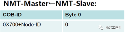
4.4 NMT BOOT-UP Messages
5 CANopen Emergency Messages
6 SDO (Service Data Object) Communication
6.1 Functions of SDO
6.2 Communication Object Identifier (COB_ID) of SDO
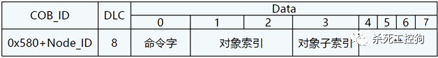
6.3 SDO Read Messages
6.4 Example of SDO Read Messages
6.5 SDO Write Messages
6.6 Example of SDO Write Messages
6.7 SDO Communication Failure Messages
7 PDO (Process Data Object) Communication
7.1 Functions of PDO
7.2 PDO Communication Parameters
7.3 PDO Communication Object Identifier (COB_ID)
7.4 Transmission Types of PDO
7.5 PDO Mapping
7.6 PDO Messages
7.7 Summary of PDO and SDO
9 Synchronization Messages
9.1 Functions of Synchronization Messages
9.2 Data Frame of Synchronization Messages
9.3 Transmission Types of Synchronization Messages
9.4 Synchronization Cycle Period and Window Time
9.5 Principle of Cyclic Synchronous Position Mode (CSP)
9.6 Impact of Synchronization Cycle on Motion Control Performance
10 Electronic Data Sheet (EDS)
Body
Controller Area Network (CAN) is one of the most widely used fieldbus systems internationally.
It is a serial communication protocol developed by Bosch in the early 1980s to solve the real-time data exchange between numerous control units and testing instruments in modern vehicles.
-
In 1983, Bosch began researching vehicle network technology.
-
In 1986, Bosch announced the CAN protocol at the SAE (Society of Automotive Engineers) conference.
-
In 1987, Intel and Philips successively launched CAN controller chips.
-
In 1991, Bosch published the CAN 2.0 technical specification, which includes parts A and B.
-
In 1991, the CAN bus was first implemented in the Benz S-Class sedan.
-
In 1993, ISO issued the international standard for CAN, ISO-11898.
-
In 1994, SAE issued the J1939 standard based on CAN.
-
In 2003, Maybach launched a new model with 76 ECUs (CAN, LIN, MOST).
-
In 2003, VW released a new Golf with 35 ECUs.
In 1992, several companies established the non-profit organization CAN in Automation (CiA) to provide information on technology, products, and marketing related to CAN. This initiative aimed to enhance the image of CAN and pave the way for its future development. As of early 2020, 670 companies had joined the CiA organization.
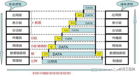
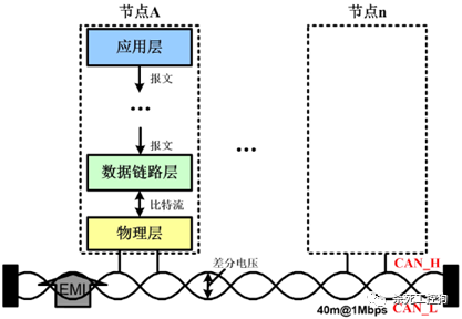
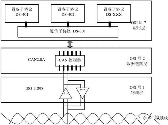
The seven-layer model, also known as the OSI (Open System Interconnection). The reference model is a standard framework established by the International Organization for Standardization (ISO) for the interconnection of computer or communication systems, commonly referred to as the OSI reference model or the seven-layer model.
From the perspective of the OSI network model, fieldbus networks generally only implement Layer 1 (Physical Layer), Layer 2 (Data Link Layer), and Layer 7 (Application Layer). Since fieldbus typically only includes one network segment, there is no need for Layer 3 (Transport Layer) and Layer 4 (Network Layer), nor for the roles of Layer 5 (Session Layer) and Layer 6 (Presentation Layer).
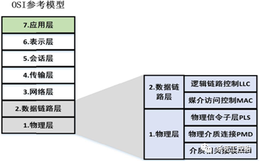
CAN only defines the physical and data link layers, with no specifications for the application layer.
The Data Link Layer includes the Medium Access Control (MAC) layer and Logical Link Control (LLC) layer, which are critical for forming data frames.
The Physical Layer, sometimes referred to as the physical interface, describes the functional description and execution procedures for establishing physical connections, providing the mechanical, electrical, functional, and procedural conditions for establishing, maintaining, and disconnecting physical connections. The physical layer has four important characteristics:
-
Mechanical Characteristics – connectors, number of pins, pin arrangement.
-
Electrical Characteristics – signal levels, impedance and impedance matching, transmission speed, and distance.
-
Functional Characteristics – functional allocation and precise definition of signal lines (data, control, ground).
-
Procedural Characteristics – operational rules and timing for each signal line.
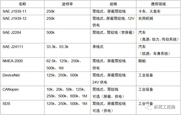
1.5 Characteristics of CAN
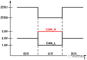
Uses a differential signal on a twisted pair, where the two wires form a bus, CAN High and CAN Low, with the voltage difference between these two wires encoding two different logical states.
The static state is around 2.5V, representing logical 1, also called a recessive bit, while CAN_H being higher than CAN_L represents logical 0, known as a dominant bit, typically with voltage values of CAN_H=3.5V and CAN_L=1.5V, where the dominant bit takes precedence in contention.
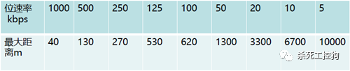
When using twisted pair as the bus medium, the bus length should be ≤40 meters, with a transmission rate of up to 1Mbps.
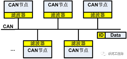
The protocol itself does not limit the number of nodes; in practice, the number of nodes is limited by the electrical characteristics of the network hardware. The number of nodes on the bus can change dynamically, with messages broadcasted being received by all nodes simultaneously.
-
Maximum bus length L: 40m.
-
Maximum branch length H: 0.3m.
-
Maximum node distance D: 40m.
-
Terminal resistance R: 120Ω.
Identifier (CAN Identifier) + 8 bytes of data.
The standard CAN identifier length is 11 bits, while the extended format CAN identifier length can reach 29 bits. The CAN protocol version 2.0A specifies that the CAN controller must have an 11-bit identifier, while version 2.0B allows the identifier length to be either 11 bits or 29 bits. CAN controllers following the CAN2.0B protocol can send and receive standard format messages with 11-bit identifiers or extended format messages with 29-bit identifiers. If CAN2.0B is disabled, the CAN controller can only send and receive standard format messages with 11-bit identifiers, ignoring the extended format message structure without error.
CAN itself is incomplete and does not define the use of the 11/29-bit identifier or the 8-byte data in CAN messages.
1.8 Common CAN Application Layer Protocols
The CAL (CAN Application Layer) protocol is one of the high-level communication protocols based on CAN, originally developed by Philips’ medical devices department.
CAL provides all network management services and message transmission protocols but does not define the content of communication objects or the types of objects being communicated (it only defines how, not what). This is precisely where CANopen comes in.
CANopen is developed based on CAL, using a subset of CAL communication and service protocols, providing a solution for distributed control systems. CANopen is an application layer protocol for CAN.
The core concept of CANopen is the device object dictionary (OD: Object Dictionary), which is also used in other fieldbus systems (Profibus, Interbus-S). It should be noted that the object dictionary is not part of CAL but is implemented in CANopen.
The CANopen protocol is license-free, allowing any organization or individual to develop devices supporting the CANopen protocol without paying licensing fees.
2.2 CANopen Network Model
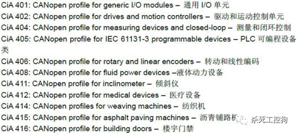
2.3 Common Standards of CANopen
The CANopen protocol is one of the standards defined by CAN-in-Automation (CiA). In Europe, CANopen is regarded as the leading standard in industrial systems based on CAN. Most important device types, such as digital and analog input/output modules, drive devices, operating devices, controllers, programmable controllers, or encoders, are described in a protocol called “device description”; “device description” defines different types of standard devices and their corresponding functions.
With the support of the CANopen protocol, devices from different manufacturers can be configured via the bus.
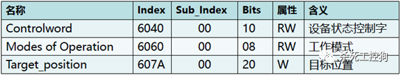
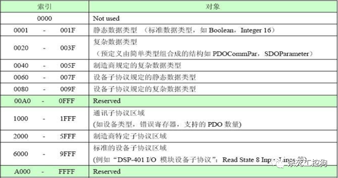
2.4 CANopen Object Dictionary
Device operations are based on the “Object Dictionary (OD)” where all parameters, parameter values, and functions are accessed and stored using a 16-bit index and an 8-bit sub-index address. In simple terms, this is the address for CANopen communication.
Each node in the CANopen network has an object dictionary. The object dictionary contains all parameters that describe the device and its network behavior.
The object dictionary of a node (including communication functions, communication objects, device-related objects, and default values of objects, etc.) is described in the Electronic Data Sheet (EDS) or recorded on paper.
The part of the object dictionary that describes communication parameters is the same for all CANopen devices (for example, the objects in the OD are the same, but the object values do not have to be identical).
The general structure of the CANopen object dictionary is as follows.
2.5 CANopen Communication Identifiers
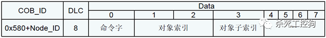
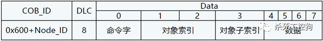
Communication Object Identifier (COB_ID) is the communication identifier. Each CANopen frame starts with a COB-ID, which is the unique identifier for the data frame.
COB_ID includes a function segment (FUNCTION) and an address segment (NODE-ID).
The Node-ID is defined by the system integrator, for example, set via a DIP switch. The Node-ID range is 1-127 (0 is not allowed).
The smaller the COB_ID, the higher the message priority. The COB_ID range for CANopen is from 0-77F.
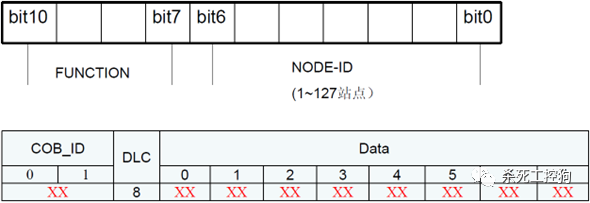
Here, DLC refers to the number of valid bytes in the data packet, ranging from 0 to 8. Data refers to the data packet (0-8 bytes of data).
3 Overview of CANopen Protocol
3.2 Communication State Machine
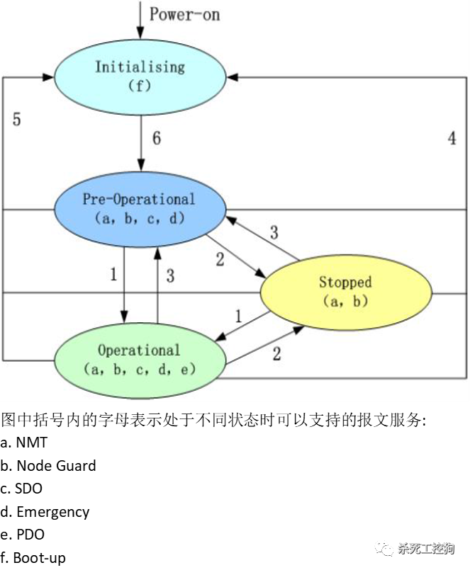
State transitions (1-5 initiated by NMT service), NMT command words (in parentheses):
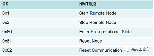
1: Start_Remote_node (0x01).
2: Stop_Remote_Node (0x02).
3: Enter_Pre-Operational_State (0x80).
4: Reset_Node (0x81).
5: Reset_Communication (0x82).
6: Device initialization ends, automatically enters Pre_Operational state, sending Boot-up message.
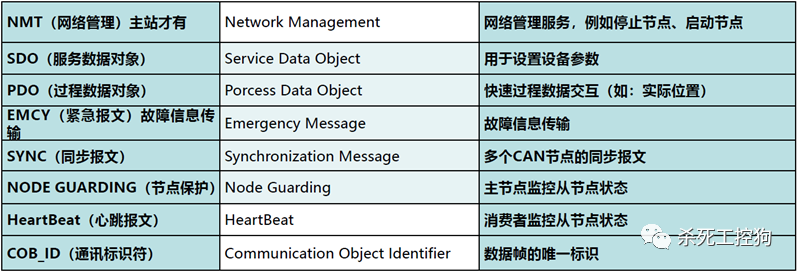
3.3 Communication Messages
CANopen communication defines four types of communication messages.
-
Network management and ID allocation services, such as initializing nodes, starting nodes, resetting nodes.
-
These services are based on a master-slave communication model, where there can only be one master node sending management messages in the CAN network.
(2) Predefined Messages or Special Function Objects
(3) Service Data Objects (SDO)
-
Using indexes and sub-indexes, SDO allows clients to access items in the device (server) object dictionary.
(4) Process Data Objects (PDO)
-
Used to transmit real-time data, with data transfer limited to 1 to 8 bytes.
4 CANopen Management Messages
4.1 NMT Module Control Messages
Only the NMT-Master node can send NMT Module Control messages. All slave nodes must support NMT module control services.
NMT Module Control messages do not require a response. The NMT message format is as follows:
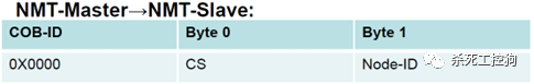
When Node-ID=0, all NMT slave devices are addressed. CS is the command word, with values and meanings as follows:
4.2 NMT Node Protection Messages
Through node protection messages, the NMT master node can monitor the current status of each slave node.
The master node periodically sends messages to inquire about the status of the slave nodes. After receiving the master node’s inquiry, the slave node replies with its status. If the master node does not receive information from the slave node within the set time or if the information is incorrect, it will determine a communication fault with the slave node.
The master node sends a remote frame (only COB-ID, no data).
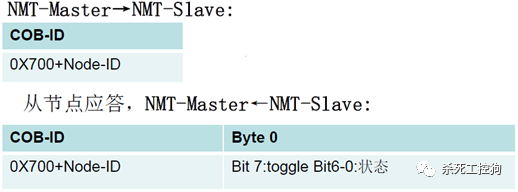
Bit7 is the trigger bit, alternating between “0” and “1” in each node protection response, starting with “0” in the first node protection.
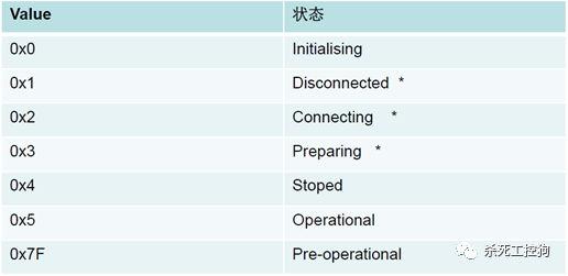
Note: The nodes marked with an asterisk are only provided by nodes that support extended BOOT-UP. State 0 never appears in node protection as the slave node does not respond during initialization.
A node can also be configured to generate periodic messages called heartbeat messages. The slave node periodically sends this message to the consumer, which can determine the status of the slave node from the status value in the message.
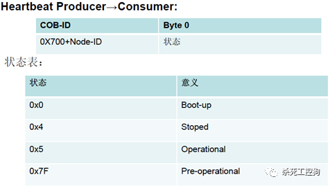
The consumer of the heartbeat message (HeartBeat) is usually the NMT-Master node, which sets a timeout for each HeartBeat node. If the timeout occurs, corresponding actions are taken.
A node cannot simultaneously use NODE-Guarding and HeartBeat.
The NMT-slave node publishes a Boot-UP message to inform the NMT-Master node that it has transitioned from the initializing state to the pre-operational state.
5 CANopen Emergency Messages
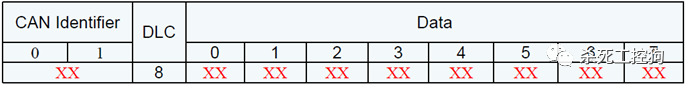
Emergency messages are triggered when a fatal error occurs within the device and are sent to other devices with the highest priority. They are suitable for interrupt-type error alarm signals. An emergency message contains 8 bytes, and the message format is as follows:
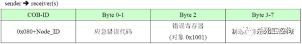
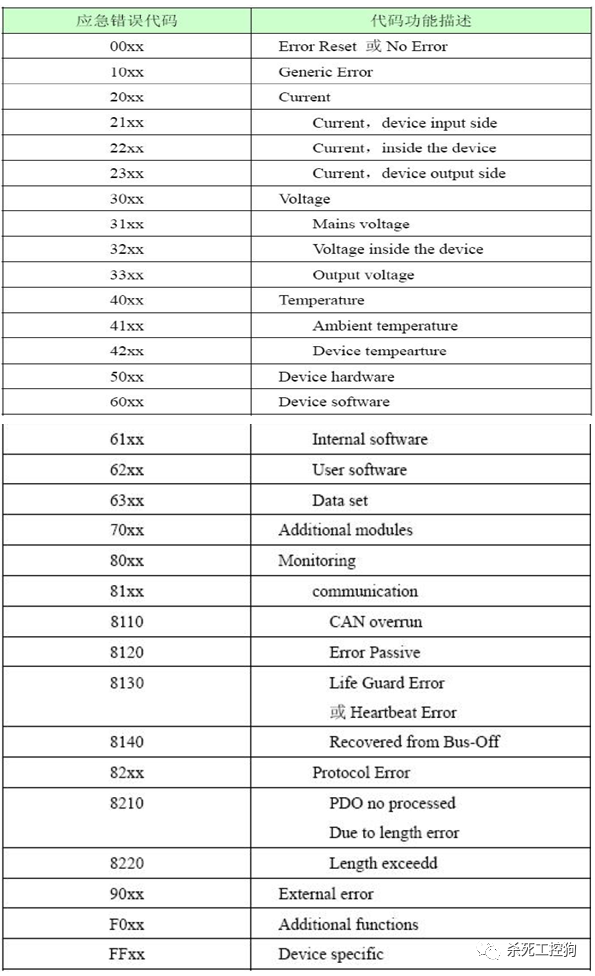
The hexadecimal emergency error codes are shown in the table below. The “xx” part of the emergency error code is defined by the corresponding device sub-protocol.
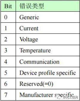
The Error Register is located in the device’s object dictionary (index 0x1001), and the table below explains the bit definitions of the error register. The device can map internal errors to this status byte for a quick overview of current errors.
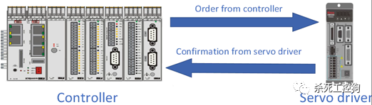
6 SDO (Service Data Object) Communication
-
SDO is mainly used to transmit low-priority objects between devices, typically for configuring and managing slave devices, such as modifying PID parameters for speed and position loops, PDO configuration parameters, etc.
-
Using indexes and sub-indexes, SDO allows clients to access objects in the device object dictionary.
-
Typically, the length of data transmitted does not exceed 4 bytes; if the data length exceeds 4 bytes, it is split into several messages.
-
The protocol is a confirmed service type: each message generates a response. SDO request and response messages always contain 8 bytes.
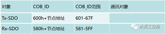
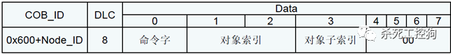
6.2 Communication Object Identifier (COB_ID) of SDO
The communication object identifier uses specific rules as follows:
** Maximum four-byte data.
Command word:
-
If the data is 1 byte, the response command word is 0x4F.
-
If the data is 2 bytes, the response command word is 0x4B.
-
If the data is 3 bytes, the response command word is 0x47.
-
If the data is 4 bytes, the response command word is 0x43.
-
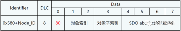
If it fails, the response command word is 0x80.
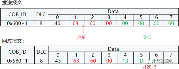
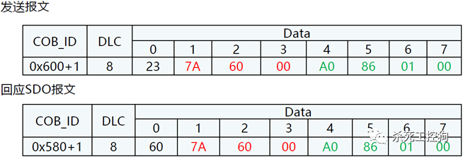
6.4 Example of SDO Read Messages
Device operations are based on the “Object Dictionary” where all parameters, parameter values, and functions are accessed and stored using a 16-bit index and an 8-bit sub-index address. In simple terms, this is the address for CANopen communication.
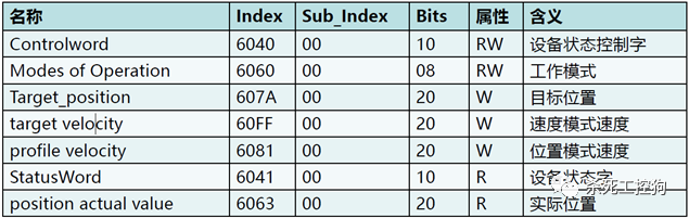
Example: Read the actual position of the servo with device station number 1, reading 4 bytes of data, CANopen data has the low byte first and high byte last, the response data is FFFFFD113HEX, converting to decimal gives -12013.
Command word:
-
If the data is 1 byte, the command word sent is 0x2F.
-
If the data is 2 bytes, the command word sent is 0x2B.
-
If the data is 3 bytes, the command word sent is 0x27.
-
If the data is 4 bytes, the command word sent is 0x23.
** The data for the write message.
Command word:
6.6 Example of SDO Write Messages
Example: Write the target position of the servo with device station number 1 to 607A0020=100000inc=000186A0HEX.
Note: CANopen data has the low byte first and high byte last.
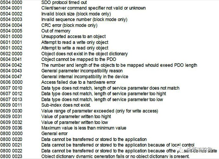
6.7 SDO Communication Failure Messages
The slave response message format is as follows:
7 PDO (Process Data Object) Communication
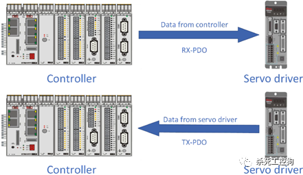
-
The CANopen protocol does not define the concept of a master node, only defining slave nodes. Therefore, RPDO and TPDO are both targeted at slave nodes. Each node has 4 TPDOs and 4 RPDOs.
-
PDO is used to transmit real-time data, with data transmitted from a producer to one or more consumers. A single PDO can transmit a maximum of 8 bytes of data at a time.
-
Each PDO is described by two objects in the object dictionary:
-
PDO communication parameters: including COB_ID, transmission type, inhibit time, timer period.
-
PDO mapping parameters: including the list of objects in the object dictionary that are mapped to the PDO, including data length. Producers and consumers interpret the contents of the PDO based on the mapped addresses.
-
The content of the message is predefined (or configured by the master node during network startup).
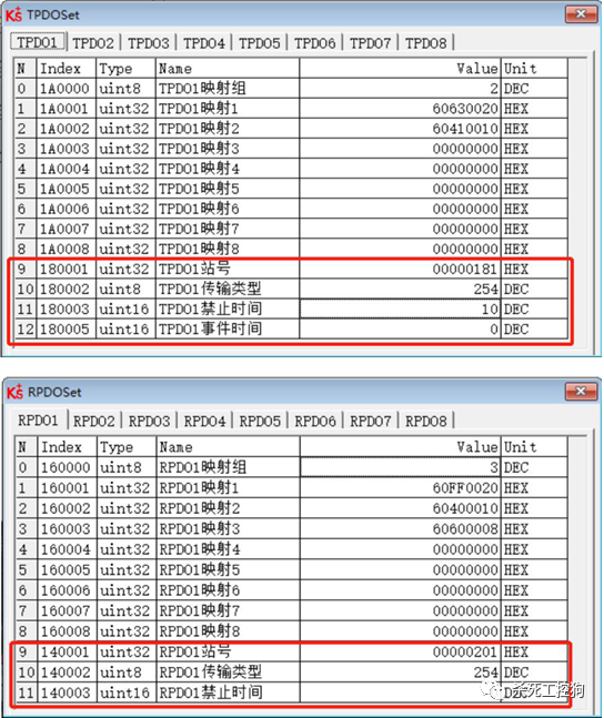
7.2 PDO Communication Parameters
Sending PDO communication parameters (1800h-19FFh) and receiving PDO communication parameters (1400h-15FFh).
PDO communication parameters describe the basic characteristics of PDOs, such as COB-ID, transmission type, inhibit time, and event timer, determining how PDOs send and receive data.
PDO inhibit time: the minimum interval time between two consecutive PDO transmissions to avoid high-priority information monopolizing the bus and preventing lower-priority data from competing for the bus. Inhibit time is defined by a 16-bit unsigned integer, for example, in Kinco servos, it is set to 1ms (the original standard is 100us).
PDO timer period: a PDO can be triggered after exceeding the timer period, defined by a 16-bit unsigned integer, with a unit of 1ms.
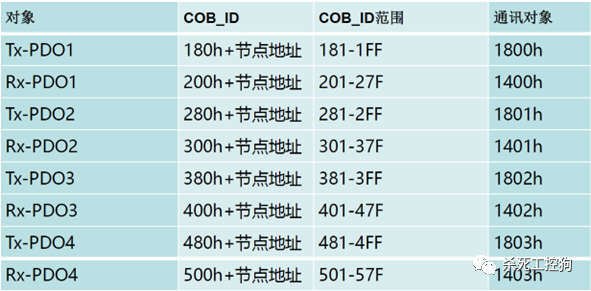
7.3 PDO Communication Object Identifier (COB_ID)
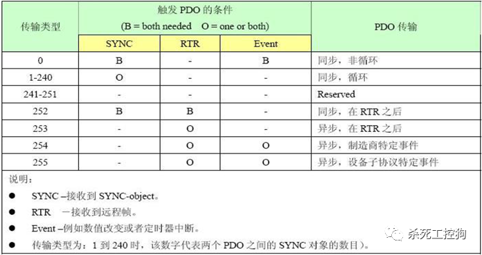
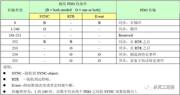
7.4 Transmission Types of PDO
Synchronization (achieved through receiving SYNC objects):
Asynchronous:
-
Triggered by specific events defined in the device protocol.
-
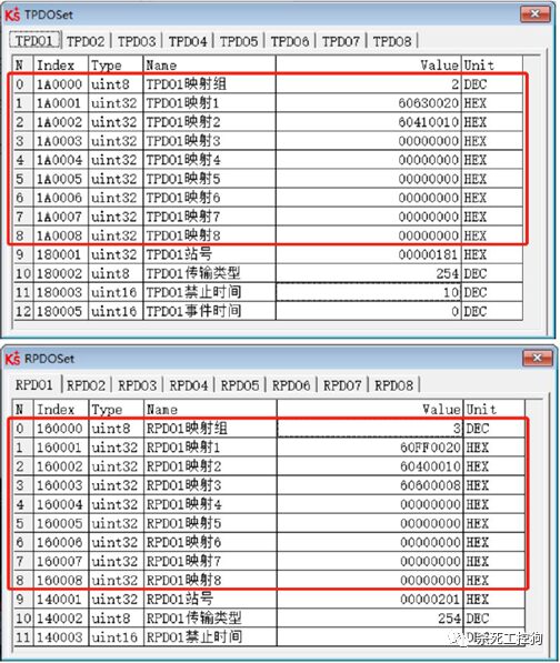
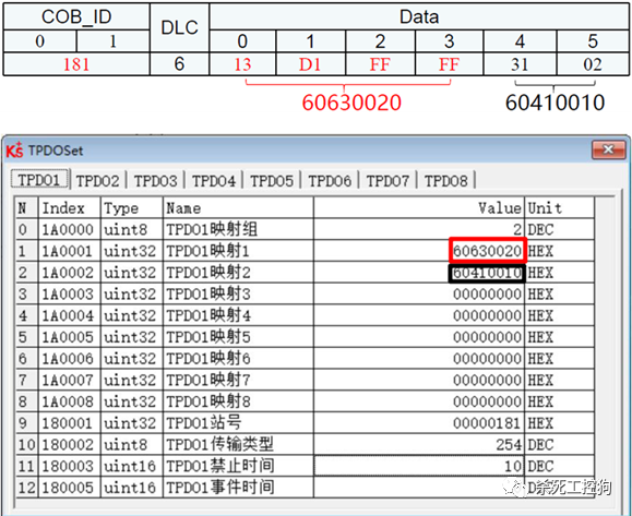
Mapping describes the communication objects contained in the PDO, determining the content of data sent or received.
-
Sending mapping (1A00h-1BFFh).
-
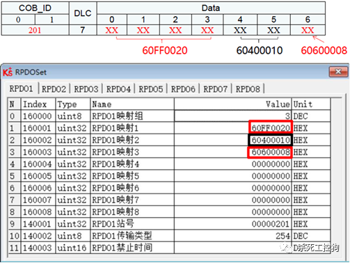
Receiving mapping (1600h-17FFh).
7.7 Summary of PDO and SDO
-
SDO communication uses a response method.
-
PDO communication uses one-way communication without requiring confirmation.
-
Slave nodes can communicate via SDO in pre-operational and operational states.
-
Slave nodes can only communicate via PDO in operational state.
Review the state machine.

9 Synchronization Messages
9.1 Functions of Synchronization Messages
9.2 Data Frame of Synchronization Messages
9.3 Transmission Types of Synchronization Messages
-
0 non-cyclic.
-
1-240 transmission types refer to how many synchronization messages are sent before sending TPDO.
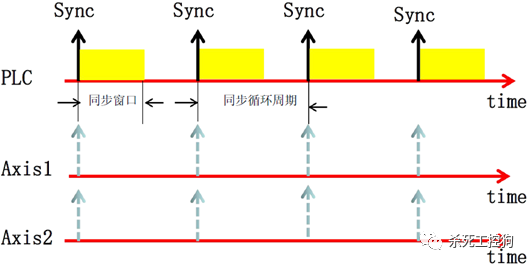
9.4 Synchronization Cycle Period and Window Time
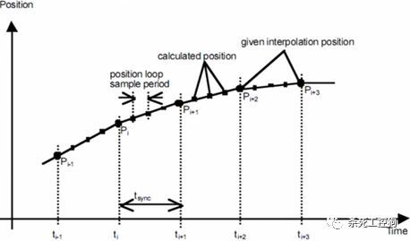
9.5 Principle of Cyclic Synchronous Position Mode (CSP)
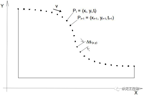
Cyclic Synchronous Position Mode (CSP) is a mode where the servo operates in interpolation mode 7. The controller completes the position instruction planning and then sends the planned target position 607A periodically synchronized to the servo driver. The controller’s target position transmission period must be an integer multiple of the servo driver’s position loop period.
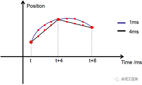
The controller periodically sends synchronization messages, such as every 1ms, 2ms, 4ms, etc., and the driver actively synchronizes its control loop frequency with the synchronization signal to achieve synchronized operation of multiple drivers.
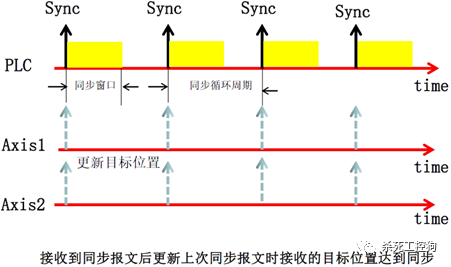
When the controller sends the RPDO to each driver, such as the target position, all drivers update their instructions simultaneously upon the arrival of the next synchronization message, achieving synchronization.
During synchronized operation mode, SDO and TPDO are also allowed, but the timing of sending must be monitored. Since RPDO is the most critical data, its reception must be prioritized, and SDO and TPDO can only be sent during idle time. A reasonable arrangement is that the first half of the synchronization cycle is used for sending SDO and TPDO, while the second half is for receiving RPDO.
After receiving the set position, the servo compares it with the current position and performs linear or nonlinear interpolation based on the controller’s cycle and the servo position loop’s cycle multiple, setting the interpolated value as the “set position” for each position loop cycle.
For example, if the servo position loop’s period is 1ms and the controller’s period is 4ms, with the servo’s current position at 300inc and the target position at 700inc, the next four cycles of the servo position loop’s “set values” will be: 400inc, 500inc, 600inc, and 700inc. If no interpolation is performed, the servo will set the position to 700inc in the first cycle, maintaining the set position unchanged for the next 2-4 position loop scanning cycles, effectively stopping the motor until the controller sends a new “target position” at 4ms. Due to the 4ms gap, the driver updates the “set position” only after this delay, resulting in a stuttering sensation, with the motor’s motion being less smooth and coherent.
The servo’s speed at this time depends on the controller’s cycle and the pulse increment for each cycle. In the above example, if the controller increases the target position by 400inc every 4ms, the servo’s operating speed will be n=400inc*1000ms/4ms=100000inc/s.
If it is a two-axis synchronization scenario, it will be as shown in the figure below.
9.6 Impact of Synchronization Cycle on Motion Control Performance
(1) Below, we calculate the relationship between the synchronization cycle of the CAN bus and the maximum number of controlled axes.
If the synchronization cycle is 1ms (1Mbit/s), the maximum number of controlled axes is 3. The calculation process is as follows:
-
The time taken by the PLC to send an RPDO: 47us (COB_ID, checksum, transmission interval, etc.) + 64us (data) = 111us.
-
The time taken by the SERVO to receive a TPDO: 47us + 64us = 111us (same as above).
-
The time taken by the PLC to send a synchronization message: 47us.
-
The total time taken to control three axes is: 222us*3 + 47us = 713us.
By analogy:
For most automation devices, CAN is sufficient. The advantage of high-speed Ethernet is that it can synchronize control for more axes.
(2) Synchronization Precision
Synchronization precision depends on the precision of the synchronization signal; high-performance servo synchronization signal jitter is generally less than 5us.
If the synchronization signal jitter is 5us, speed is 3000RPM, resolution is 10000, and the synchronization cycle is 4ms, then every 4ms updates 2000inc, making 5us equal to 2.5inc, meaning the jitter precision of 5us is ±2.5inc.
High-speed Ethernet has an advantage over CAN bus in synchronization precision; for instance, Ethercat’s synchronization signal jitter is less than 1us, but for most applications, CAN bus synchronization precision is already sufficient.
Synchronization precision is independent of the synchronization cycle; the difference between 1ms and 4ms lies in the smoothness of the positioning process, not in the deviation of the positioning result.
10 Electronic Data Sheet (EDS)
The EDS (Electronic Data Sheet) file is an identification file for the slave connected to the PLC, used to identify the type of the slave. This file contains all information about the slave, such as manufacturer, serial number, software version, supported baud rates, mappable OD, and the properties of each OD, similar to the GSD file in Profibus. Therefore, before performing hardware configuration, we first need to import the EDS file of the slave into the upper-level configuration software to communicate with it.
Fieldbus and industrial Ethernet have become important industrial control communication networks. In recent years, wireless sensor networks and the Internet of Things (IoT) have also integrated into industrial measurement and control systems. This book details CAN, PROFIBUS, CC-LINK, wireless sensor networks, IoT technology, embedded networks, industrial Ethernet, and other contents. Those who wish to understand more can read it.