Follow our official account to never miss any updates!

This tutorial was originally published by the author strongerHuang in October 2018.
Tags: CAN, CANOpen, CanFestival
Copyright: Commercial use is prohibited
Disclaimer:This document is for personal learning use only. Please contact the author via the official account for authorization if you wish to reprint.
1Introduction
This tutorial covers many concepts about the CAN protocol, which may be confusing for beginners. This article will help you understand the previously discussed content through code examples.
Since most of my followers are learning STM32, I will use STM32F103 and the standard peripheral library examples to help you understand some concepts discussed earlier.
This article primarily discusses:
1. Data Transmission Parameters
2. Bit Timing and Transmission Baud Rate
To facilitate understanding, I will provide the corresponding example at the end: CANOpen Tutorial 06_CAN Data Transmission Example. Of course, this article will only cover parts of the code; some configuration parameters will be discussed later.
2
Data Transmission Parameters
The data transmission parameters mainly refer to the content discussed in the previous CANOpen Tutorial 04 in the chapter on “Frame Types and Format Description.” It is recommended to review those concepts first.
The content transmitted over the CAN bus mainly involves sending and receiving. Below, I will use the parameters for sending and receiving in the code to help you understand how we control the parameters on the CAN bus through programming.
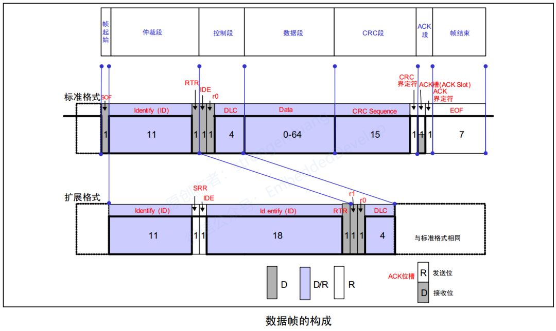
2.1 CAN Bus Data Frame
This article provides examples primarily based on the most commonly used data frame in CAN bus, to help everyone understand the parameters we control in data frame transmission via programming.
First, let’s review the data frame format in the image below. Some fields are automatically completed by the controller, such as frame start and CRC check. Others are controlled by our programming, such as ID, data, etc.
2.2 CAN Sending Code
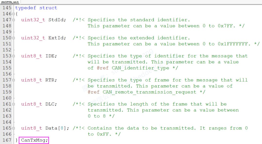
A. CAN Sending Data Structure
The image below mainly shows the parameters controlled by our programming when sending CAN data. You will notice that they mainly correspond to the frame format above: ID, IDE, RTR, DLC, Data.
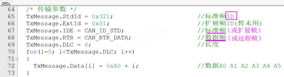
B. Sending Configuration Parameters
The image below shows the actual parameters for sending configuration.
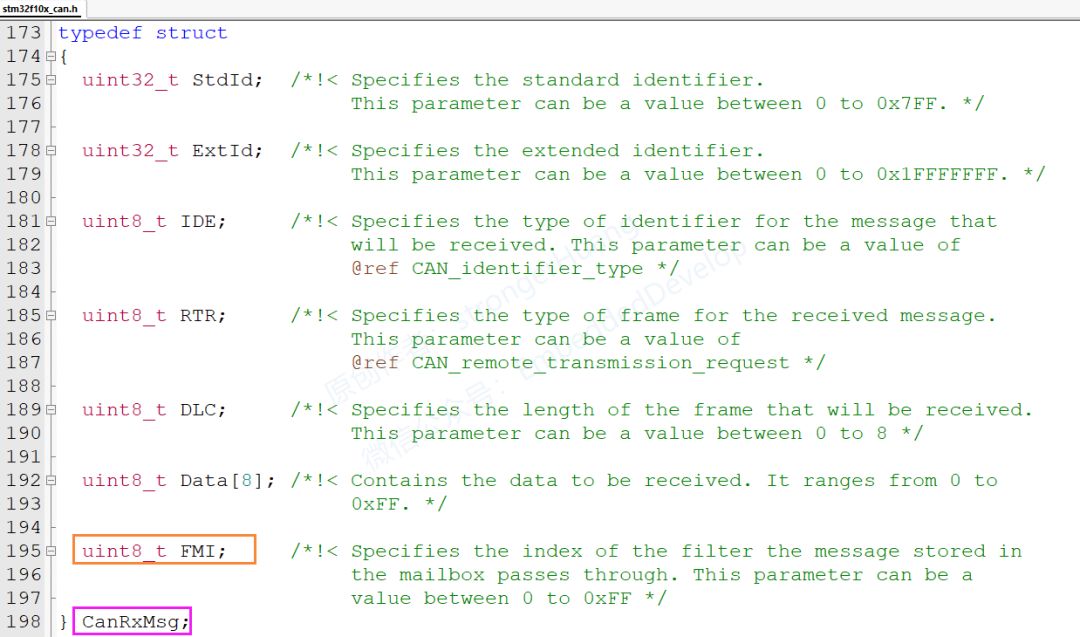
2.3 CAN Receiving Code
Receiving CAN data is similar to sending. The fields on the CAN bus are the same; the parameters received at the receiving end are simply those sent by the sender.
For the CAN integrated within STM32, the receiving data structure has an additional FMI parameter, which essentially means the index of the receive message mailbox filter.
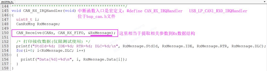
Receiving Operation
To facilitate beginners’ understanding, here we will use interrupts to receive CAN bus data. Printing in the interrupt function is mainly for testing; generally, printing will not occur in the interrupt function in actual projects (printing is relatively time-consuming).
3
Bit Timing and Transmission Baud Rate
Similarly, the concept of “bit timing and transmission baud rate” was discussed in the previous CANOpen Tutorial 04. In fact, bit timing indirectly determines the transmission baud rate. In other words, the transmission baud rate is determined by several parameters of bit timing.
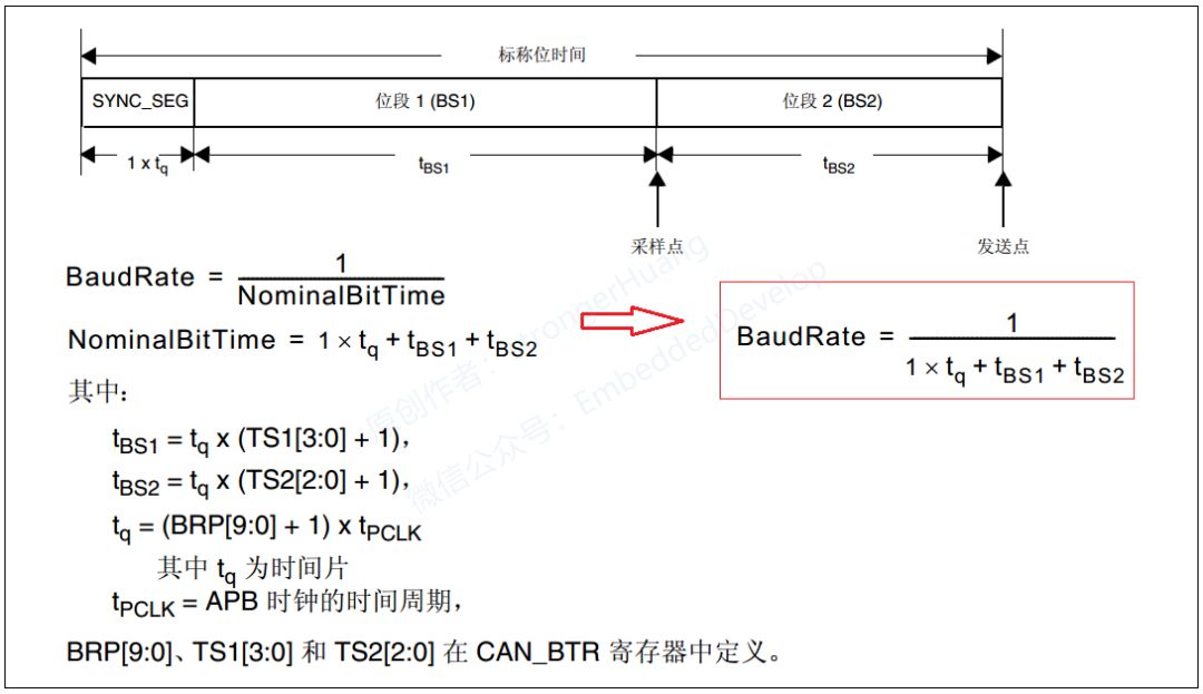
Let’s look at the image below to review the baud rate calculation formula:
3.1 Baud Rate Configuration Code
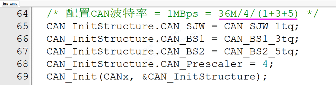
Combining the calculation formula from the above image and the code in the next image, we can see the relationship between several parameters in bit timing and baud rate. When the baud rate is 1M, the bit timing parameters can be configured as shown in the image below:
Note:
36M represents the CAN clock; specific configurations depend on the clock settings.
The baud rate is fixed, but the bit timing parameters can vary. For example, if the baud rate is fixed at 1M, the bit timing parameters can be set as shown in the image; you can also modify some of the values, such as changing segment 1 to CAN_BS1_5tq and segment 2 to CAN_BS2_3tq. Just follow the baud rate calculation formula.
4
Example Download
CANOpen Tutorial 06_CAN Data Transmission Example:
https://pan.baidu.com/s/1LzD0Epc-Z8vlHsb-sD3WVw
Extraction Code: l2dc
Note:
The link may become invalid later; you can reply with [CANOpen Tutorial] to check for updated links.
5
Remarks
1. Some content of this document comes from the internet and is for personal learning use only. Copyright reserved; commercial use is prohibited.
2. This article was edited and compiled by me alone, and it may contain some errors.
3. This article is included in the official account “strongerHuang”. Follow the official account and reply with [CANOpen Tutorial] to view the entire series of tutorials.
6Conclusion
If you find this article helpful, remember to like and share it. (Likes are the motivation for the author to update articles)
Scan the QR code below to follow and see more exciting content in the bottom menu!

Long press to recognize the QR code in the image to follow

Appreciation is recognition and support for the author!