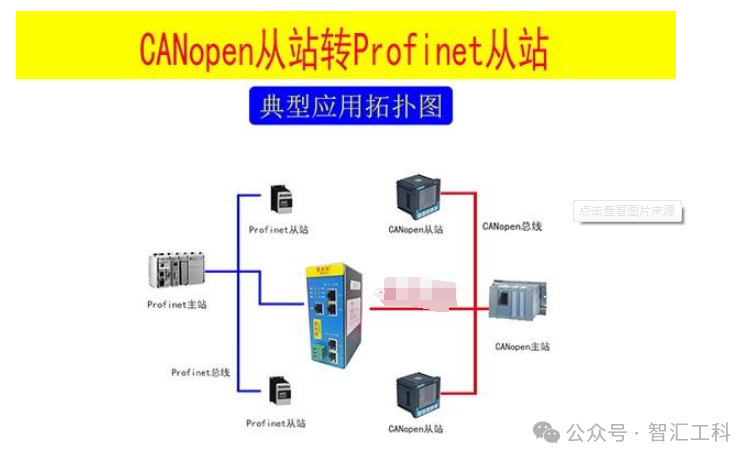
Connecting a CANOpen to PROFINET gateway with low voltage servo systems is a common application scenario in the field of industrial automation. Below is a detailed analysis of the connection process:
1. Preparation Work
1. Hardware Preparation:
● CANOpen to PROFINET gateway
● Low voltage servo system (with CANOpen interface)
● PLC (with PROFINET interface)
● Connection cables (such as Ethernet cables, CAN bus cables, etc.)
2. Software Preparation:
● PLC programming software (such as Siemens TIA Portal)
● CANOpen to PROFINET gateway configuration software
● EDS (Electronic Data Sheet) file for the low voltage servo system
2. Configuration Steps
1. Install the GSD file:
● Select the directory where the GSD file provided by the CANOpen to PROFINET gateway supplier is located and install it. The GSD file describes the characteristics of the PROFINET device and is used for device configuration in the PLC programming software.
2. Device Configuration:
● In the PLC programming software, drag the CANOpen to PROFINET gateway into the device view through the device and network.
● Connect the PLC to the gateway; once connected, a dashed line will appear indicating the connection.
● Double-click the gateway icon to enter the device view, and set the gateway’s IP address, subnet mask, and device name. Ensure the IP address is in the same subnet as the PLC, and the device name matches the gateway.
3. Configure Gateway Parameters:
● In the gateway configuration software, import the EDS file of the low voltage servo system. The EDS file contains the communication parameters and configuration information for the servo system.
● Add master and slave devices, and set the baud rate, cyclic transmission interval, and other parameters for the slave. These parameters should be set according to the requirements of the servo system.
4. Set PDO Parameters:
● PDO (Process Data Object) is an object used for transmitting process data in CANOpen communication. In the gateway configuration software, set the transmission type of RPDO (Receive PDO) and TPDO (Transmit PDO) to cyclic synchronous or trigger mode.
● Right-click on PDO to add indexed parameters as needed. RPDO corresponds to the gateway’s transmission, while TPDO corresponds to the gateway’s reception. Ensure that the mapped parameters align with the actual control requirements of the servo system.
5. Download Configuration and Test:
● Download the configured parameters to the PLC and gateway.
● Power cycle the CANOpen to PROFINET gateway and observe the status of the gateway’s indicator lights. If the OK light is on and the err light is off, the hardware connection of the gateway is normal.
● Monitor the communication messages through the PLC programming software to ensure data is transmitted correctly.
3. Precautions
1. Correct Wiring: Ensure that all connection cables are wired correctly; otherwise, communication will not function properly.
2. Parameter Matching: When setting PDO parameters, ensure that the mapped parameters align with the actual control requirements of the servo system to avoid control errors.
3. Consistent IP Addresses: When setting the IP addresses for the gateway and PLC, ensure they are in the same subnet and that the device names match to ensure smooth communication.
4. Software Version Compatibility: Ensure that the versions of the PLC programming software and gateway configuration software are compatible to avoid communication issues due to incompatibility.
In summary, connecting a CANOpen to PROFINET gateway with a low voltage servo system requires a series of preparation and configuration steps. With correct configuration and testing, stable communication and control between the servo system and PLC can be achieved.